
Combined inspection system including mid-ir vibrational spectroscopy and a fluorescent cytometry facility

a fluorescent cytometry and vibrational spectroscopy technology, applied in the field of cell measurement based on midinfrared absorption measurement, can solve the problems of low accuracy and safety concerns, no safe and accurate method for cell sorting, and the facs process has been shown

Inactive Publication Date: 2012-08-02
1087 SYST
View PDF7 Cites 47 Cited by
  • Summary
  • Abstract
  • Description
  • Claims
  • Application Information

AI Technical Summary

Benefits of technology

This approach enables accurate, high-throughput cell sorting with reduced risk of cell damage, achieving purities of over 99% in sorting sperm cells by X and Y chromosomes, and allows for precise measurement of cellular components without the need for labels or dyes.

Problems solved by technology

There is currently no safe and accurate method for cell sorting.
There are two major disadvantages to this method applied to certain cells, including low accuracy and safety concerns.
In sperm cell sorting, the FACS process has been shown to cause chromosomal damage in sperm cells as a result of the dyes used, and as a result of exposure to high intensity 355 nm laser light.
However, these chemical markers may damage or alter the function of the target cells, which is particularly disadvantageous for live cell sorting.
In testing, dyes used as markers for DNA, for example, have resulted in chromosomal damage.
Further, the intense UV or visible light used to read the level of marker in the cell may damage the cell, in particular, DNA damage results from exposure to high-energy UV or visible photons.
Also, because of the wavelengths used in so called fluorescence activated cell sorting (FACS) systems, quantitative measurements (rather than yes / no measurements for a particular antibody) are made very difficult, because both the illuminating wavelength and the emitted fluorescence are scattered and absorbed by cellular components.
This means that cell orientation becomes an important factor in accurate measurement, and can dramatically reduce the effectiveness of the system.
With Raman spectroscopy, the individual photon energy is generally lower than that used for fluorescent markers, however, the net energy absorbed can be very high and unsafe for live cells.
One significant drawback of mid-IR spectroscopy is the strong absorption by water over much of the “chemical fingerprint” range.
This has strongly limited the application of Fourier Transform Infrared Spectroscopy (FTIR) techniques to applications involving liquid (and therefore most live cell applications) where long integration times are allowable—so sufficient light may be gathered to increase signal-to-noise ratio and therefore the accuracy of the measurement.
The lack of availability of high-intensity, low etendue sources limit the combination of optical path lengths and short integration times that may be applied.
In addition, because of the extended nature of the traditional sources used in FTIR, sampling small areas (on the order of the size of a single cell) using apertures further decimates the amount of optical power available to the system.
Again, however, the coupling into the substance of interest is very shallow, typically restricted to microns.
Furthermore, one of the problems raised in mid-IR microspectroscopy is that of scattering.
Problems encountered center about the measurement of high-index cells using FTIR.
Scattered light that is not captured by the instrument is misinterpreted as absorption, and results in artefacts in the Fourier-inverted spectrum.
This causes additional index mismatch between the medium and cells, dramatically raising scattering efficiency and angles; 2) Measurement of absorption peaks at high wavenumbers (short wavelengths) where scattering efficiency is higher; 3) Insufficient capture angle on the instrument.

Method used


Image

  • Combined inspection system including mid-ir vibrational spectroscopy and a fluorescent cytometry facility
  • Combined inspection system including mid-ir vibrational spectroscopy and a fluorescent cytometry facility
  • Combined inspection system including mid-ir vibrational spectroscopy and a fluorescent cytometry facility

Examples


Embodiment Construction

)

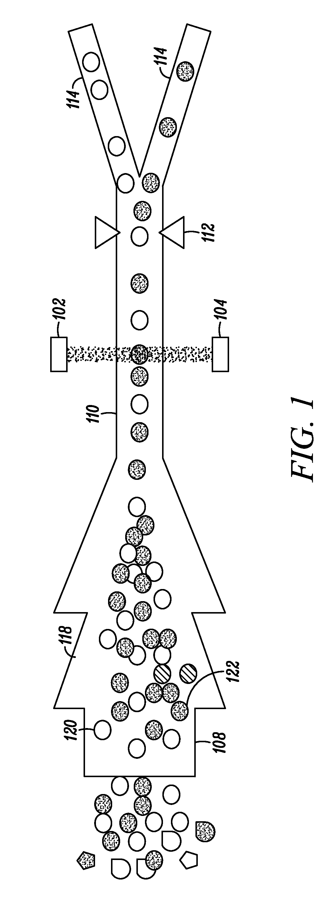
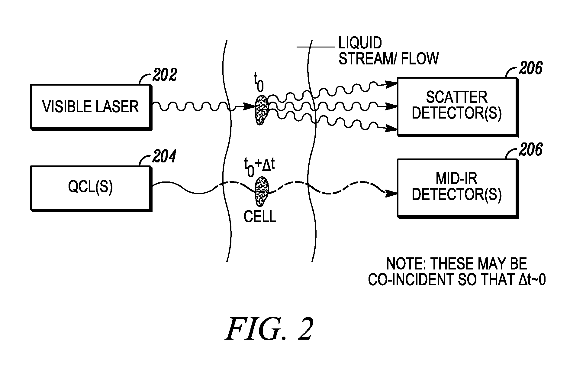
[0099]The invention described herein presents a novel approach to cellular measurements based on mid-infrared absorption measurements. Mid-IR quantum cascade lasers (QCLs) have the potential to focus sufficient energy onto a single cell to make an accurate, high-speed measurement. QCLs have recently been commercialized by multiple vendors. They are built using the same processes and packaging as high-volume telecom lasers. QCLs offer several advantages over traditional mid-IR sources such as delivering very high spectral power density, delivering very high spatial or angular power density, among other advantages. This allows QCLs to put 10,000,000× more effective mid-IR power onto a single cell than traditional mid-IR sources. This disclosure seeks to describe certain applications enabled by QCLs, such as label-free detection without dyes or labels that can alter or damage cells, measurements using mid-IR illumination 25× less energetic than that used in FACS, eliminating photon da...


PUM

PropertyMeasurementUnit
channel depthaaaaaaaaaa
wavelength rangeaaaaaaaaaa

Abstract

This disclosure concerns a cytometry system including a handling system that presents single cells to at least one quantum cascade laser (QCL) source. The QCL laser source configured to deliver light to a cell within the cells in order to induce resonant mid-infrared absorption by one or more analytes of the cell. The system includes a laser source that excites at least one fluorophore present in the cell or on the surface of the cell and a fluorescence detector that measures the fluorescence intensity of the fluorophore. A mid-infrared detection facility detects the transmitted mid-infrared wavelength light, wherein the transmitted mid-infrared wavelength light and the fluorescence intensity are used to identify at least one cell characteristic.

Description

CROSS-REFERENCE TO RELATED APPLICATIONS[0001]This application claims the benefit of U.S. Provisional Application No. 61 / 628,259, filed Oct. 27, 2011 which is hereby incorporated by reference herein in its entirety. This application is a continuation of the following U.S. patent application, which is hereby incorporated by reference herein in its entirety: U.S. Non-Provisional Patent Application No. 13 / 298,148, filed Nov. 16, 2011, which claims the benefit of the following provisional applications, each of which is hereby incorporated by reference herein in its entirety:[0002]U.S. Provisional Application No. 61 / 456,997, filed Nov. 16, 2010;[0003]U.S. Provisional Application No. 61 / 464,775, filed Mar. 9, 2011;[0004]U.S. Provisional Application No. 61 / 516,623, filed Apr. 5, 2011;[0005]U.S. Provisional Application No. 61 / 519,567, filed May 25, 2011;[0006]U.S. Provisional Application No. 61 / 571,051, filed Jun. 20, 2011; and[0007]U.S. Provisional Application No. 61 / 575,799, filed Aug. 29,...

Claims


Application Information

Patent Timeline
Patent Type & Authority Applications(United States)
IPC IPC(8): C12M1/34
CPCC12N5/0612G01N15/1434G01N15/147G01N21/3563G01N2015/149G01N2015/1497B07C5/34G01N15/1484G01N2015/1493G01N15/1429G01N15/1427B01L3/502761G01N15/1459G01N2015/1006G01N21/35G01N21/65G01N2021/653G01N29/2418G01N2291/02466G01N15/1433G01N2015/1481G01N15/1492G01N15/1436G01N15/14G01N21/1702B01L2200/0652B01L2300/0864G01N2201/0612B01L2300/0627B01L2200/0636G01N15/01G01N15/149
Inventor WAGNER, MATTHIASHEANUE, JOHN
Owner 1087 SYST
Learn More