
Target system

a target system and target technology, applied in the field of targets, can solve the problems of reducing the risk of an officer accidentally firing at a person, reducing the risk of an officer being shot at, and often not being able to advance, so as to minimize the damage to the target

Active Publication Date: 2012-08-02
ACTION TARGET
View PDF11 Cites 15 Cited by
  • Summary
  • Abstract
  • Description
  • Claims
  • Application Information

AI Technical Summary

Benefits of technology

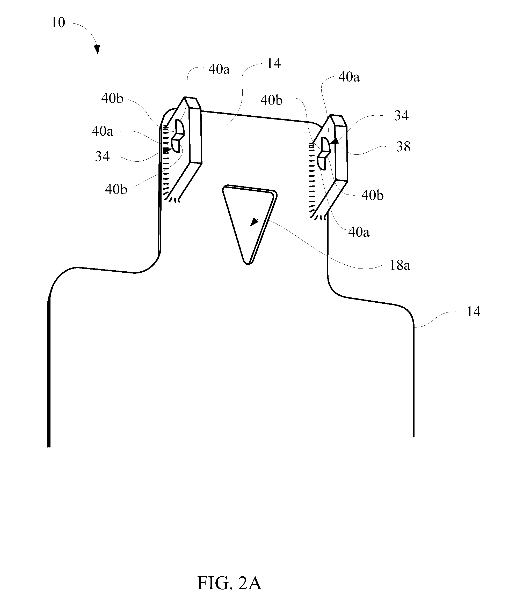
[0012]In accordance with one aspect of the invention, the target may be attached to the blocking plate or a structure positioned behind the blocking plate by a hinge mechanism to enable the target to pivot when hit by a bullet or other projectile. The hinge mechanism, in one embodiment of the invention, allows the target to be attached to and removed from the hinge mechanism without the use of tools. Tool less attachment of the targets to the hinge mechanism allows the target to be mounted on or in the hinge mechanism and removed therefrom in a matter of seconds, thereby facilitating the changing of target plates.
[0019]In accordance with still yet another aspect of the present invention, the plurality of targets may comprise targets having different mass to thereby allow the target to move appropriately in response to a given class of projectile, while minimizing damage to the target. Thus, for example, the target may be made from ¼th inch soft steel for being shot with a 22 caliber pistol, and be replaced with a ½ inch piece of hardened steel for being shot by a high powered rifle.

Problems solved by technology

Such split-second decisions can mean the difference between life and death both for the officer and the potential threat.
This can lower the risk of an officer accidentally firing at a person who is not an actual threat or hesitating too long to shoot at a person who is endangering the life of the officer or others who are nearby.
The officer often will not be able to advance until the target has been hit in the kill zone.
For example, shooting at a target and then retrieving the target to see where it has been hit is often less desirable than allowing the officer to see a visual response in the target itself immediately after the shot.
However, with many existing target designs, changing the targets can be time consuming and burdensome.

Method used


Image

  • Target system
  • Target system
  • Target system

Examples


Embodiment Construction

[0032]Embodiments of target systems and associated methods as shown in the accompanying drawings, which include reference numerals referred to below, provide details for understanding and practice by one skilled in the art. The drawings and descriptions are exemplary of various aspects of target systems and associated methods and are not intended to narrow the scope of the appended claims.

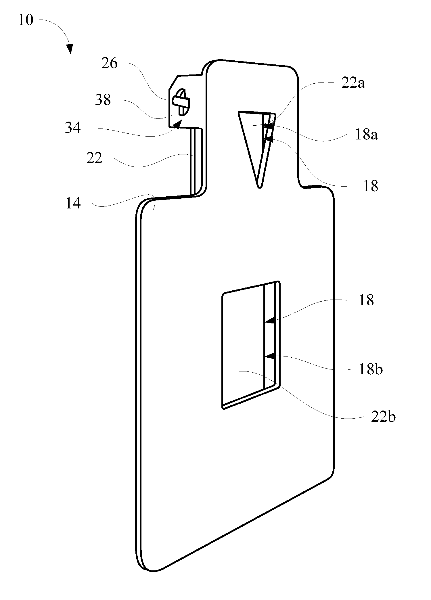
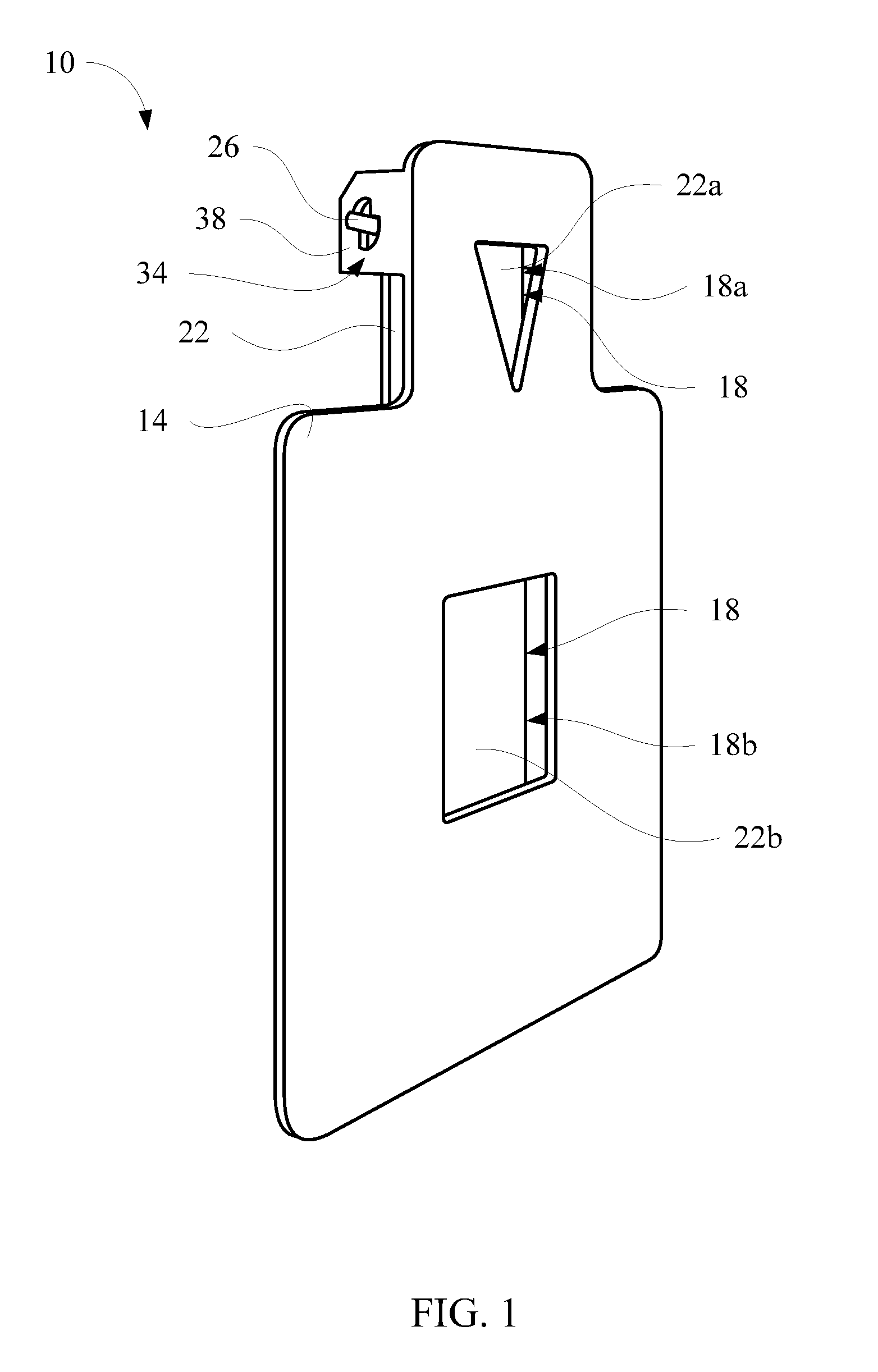
[0033]Turning now to FIG. 1, a perspective view of a target system 10 is shown. The target system 10 includes a blocking plate 14. The blocking plate 14 may be of any particular shape. However, it may be preferred to have the blocking plate 14 to have a generally similar shape as the expected real life target associated with a particular tactical situation. Thus, as shown in FIG. 1, the blocking plate 14 is in the general silhouette of a person. However, other blocking plate shapes could be used. For example, if training to disable a vehicle, a blocking plate may be in the shape of a vehicle. If be...


PUM

PropertyMeasurementUnit
rotationaaaaaaaaaa
rotationaaaaaaaaaa
massaaaaaaaaaa

Abstract

A target system includes a blocking plate with one or more openings through which bullets are fired and one or more targets for being struck by the bullets disposed behind the blocking plate and generally in line with the one or more openings. The target system may include a hinge mechanism which limits the range of movement of the target after it has been struck by a projectile. The hinge mechanism may also provide for tool less attachment and removal of the targets from the hinge mechanism.

Description

PRIORITY[0001]The present application claims the benefit of U.S. Provisional Patent Application Ser. No. 61 / 433,513, filed Jan. 17, 2011, which is incorporated herein by reference in its entirety.THE FIELD OF THE INVENTION[0002]The present invention relates to targets used for target practice. More specifically, the present invention relates to target systems which can be readily modified to facilitate different target training exercises.BACKGROUND[0003]In order to maintain proficiency in the use of firearms, it is common for law enforcement officers, members of the military and sportsmen to engage in target practice. While many perceive target practice as simply a method for improving accuracy, it is important for law enforcement officers and the like to conduct target practice in scenarios which improve timing and the ability to make split-second decisions on whether or not to fire. Such split-second decisions can mean the difference between life and death both for the officer and...

Claims


Application Information

Patent Timeline
Patent Type & Authority Applications(United States)
IPC IPC(8): F41J1/00B23P11/00
CPCF41J5/18Y10T29/49826F41J7/04F41J1/01F41J13/02F41J1/10
Inventor HENSON, BLAINETURNER, JEFFREY
Owner ACTION TARGET
Learn More