
Vehicle position lamp and headlight

a technology for vehicle position lamps and headlights, which is applied in the field of vehicle position lamps, can solve the problems of reducing the light intensity and a variation of the light intensity of the vehicle position lamps, complicated work in the assembly process, and inspection process, and achieves the effects of simple structure, high merchantability, and ease of workability

Inactive Publication Date: 2012-07-26
STANLEY ELECTRIC CO LTD
View PDF1 Cites 7 Cited by
  • Summary
  • Abstract
  • Description
  • Claims
  • Application Information

AI Technical Summary

Benefits of technology

[0023]In the above-described exemplary vehicle position lamp, the at least one connecting plate can be configured to receive a part of light from the inner surface of the one of the adjacent optical plates, and also the inner surface thereof can include a concave surface toward the outer surface thereof in order to efficiently emit light from the at least one connecting plate toward the second inner lens. In addition, the inner surface of each of the optical plates can include a plurality of linear prisms that extend at least one of in a direction parallel to the substantially same virtual surface and in a direction perpendicular to the substantially same virtual surface so as to efficiently emit a diffusing light from the diffusing lens in accordance with a shape of the second inner lens. The mounting surface and the rear surface of each of the circuit boards can include a metallic foil to prevent each of the LEDs from a positional misalignment due a heat.
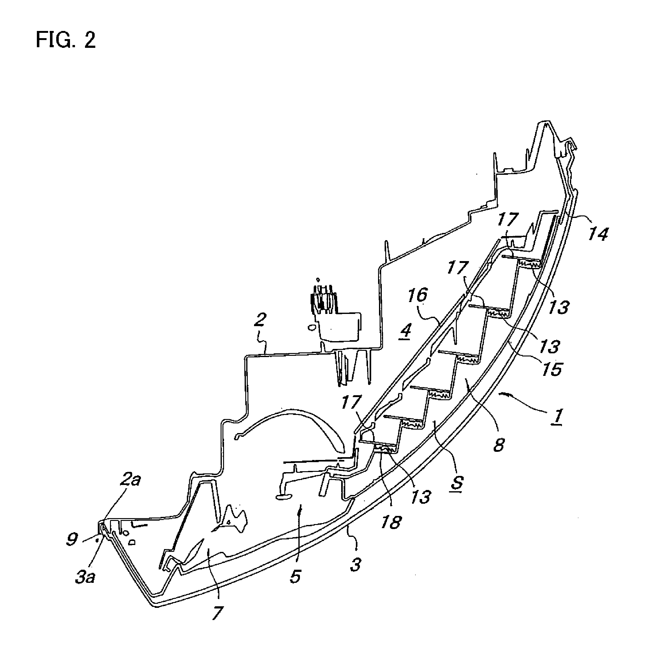
[0024]Moreover, in the above-described exemplary vehicle position lamp, the at least one connecting plate includes a plurality of connecting plates each having a length between the adjacent optical plates, wherein the length of each of the connecting plates is configured to become gradually short in the light-emitting direction of each of the white LEDs, so that the vehicle position lamp can provide a favorable light distribution along the outer lens having various curved shapes. The vehicle position lamp can further include at least one fixing seat located adjacent the inner surface of each of the optical plates and at least two stays included in the second inner lens, in order to ease a workability for fixing the circuit boards and for an assembly thereof.
[0025]According to the above-described exemplary vehicle headlight, because the diffusing lens of each of the optical plates of the at least one first inner lens that can be formed in various slender curved shapes so as to match the shape of the second inner lens can be arranged along the second inner lens, the vehicle position lamp can provide light having a high visibility. In addition, because light can also be emitted from the at least one connecting plate connecting the optical plates, the vehicle position lamp can provide light having a high visual quality using the at least one first inner lens. Moreover, because the at least one first inner lens can be integrated as an all-in-one package, the optical axis of the diffusing lens of each of the optical plates of the at least one first inner lens may easily correspond to the optical axis of each of the white LEDs. Thus, the disclosed subject matter can provide vehicle position lamps having a favorable light distribution with a simple structure, such that can ease a workability in the manufacturing processes and can reduce a positional misalignment between the optical axes.
[0028]According to an exemplary vehicle headlight, because the vehicle position lamp can be formed in various slender curved shapes such that is easily incorporated into a narrow space in the lamp room between the curved outer lens and the housing, which matches both front corners of a vehicle. Thus, the vehicle headlight can functionally incorporate the low beam headlight, the high beam headlight and the like along with the position lamp with a simple structure such that can ease a workability. Furthermore, the vehicle position lamp using the white LEDs can emit light having a substantially white color tone that is formed in various slender curved shapes. Thus, the disclosed subject matter can provide vehicle headlights having a high merchantability and a high visual quality, which can emit harmonious light having a substantially same white color tone from the position lamp and the headlights having a light source such as the HID bulb and the white LED light source.

Problems solved by technology

The Patent Documents relate to the vehicle signal lamps such as a stop lamp, a tail lamp and the like, which need a relative large light-emitting surface, and the structures disclosed in the Patent Documents may be difficult to adapt a vehicle signal lamp such as a position lamp.
However, when the vehicle position lamp having the slender curved shape is designed using the structure disclosed in Patent Document No. 1, each directional quality of light emitted from the LEDs 37 degrades in a portion having a large curved surface of the outer lens and therefore, may cause a decrease of light intensity and a variation of the light intensity of the vehicle position lamp.
Moreover, when the vehicle position lamp having the slender curved shape is designed using the structure disclosed in Patent Document No. 2, each high positional accuracy between the plurality of LEDs 44 and the plurality of Fresnel lenses 45 may be required to maintain a visibility and a visual quality of the vehicle position lamp, and thus may cause a complicated work in an assembling process, an inspection process, etc.

Method used


Image

  • Vehicle position lamp and headlight
  • Vehicle position lamp and headlight
  • Vehicle position lamp and headlight

Examples


Embodiment Construction

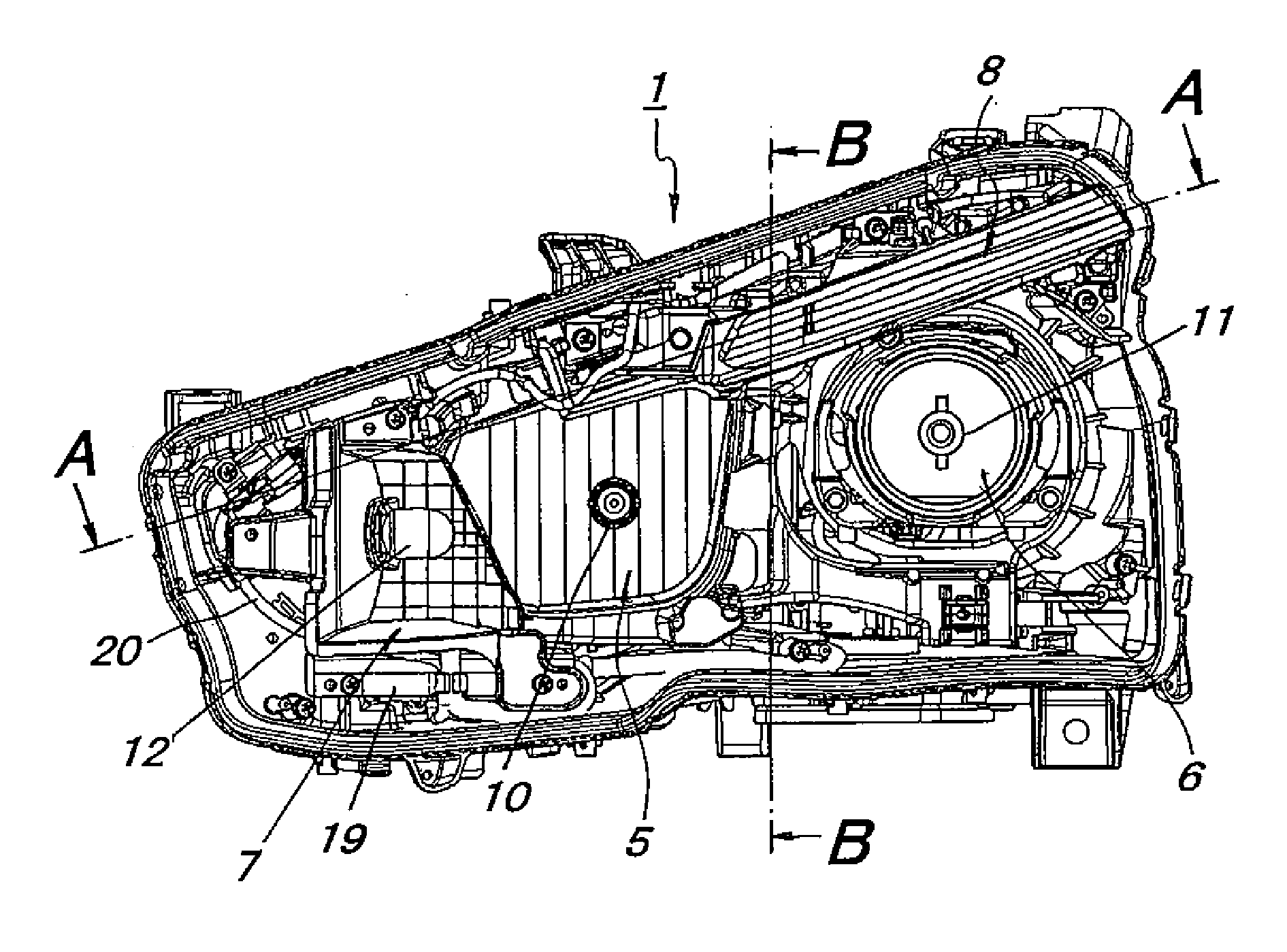
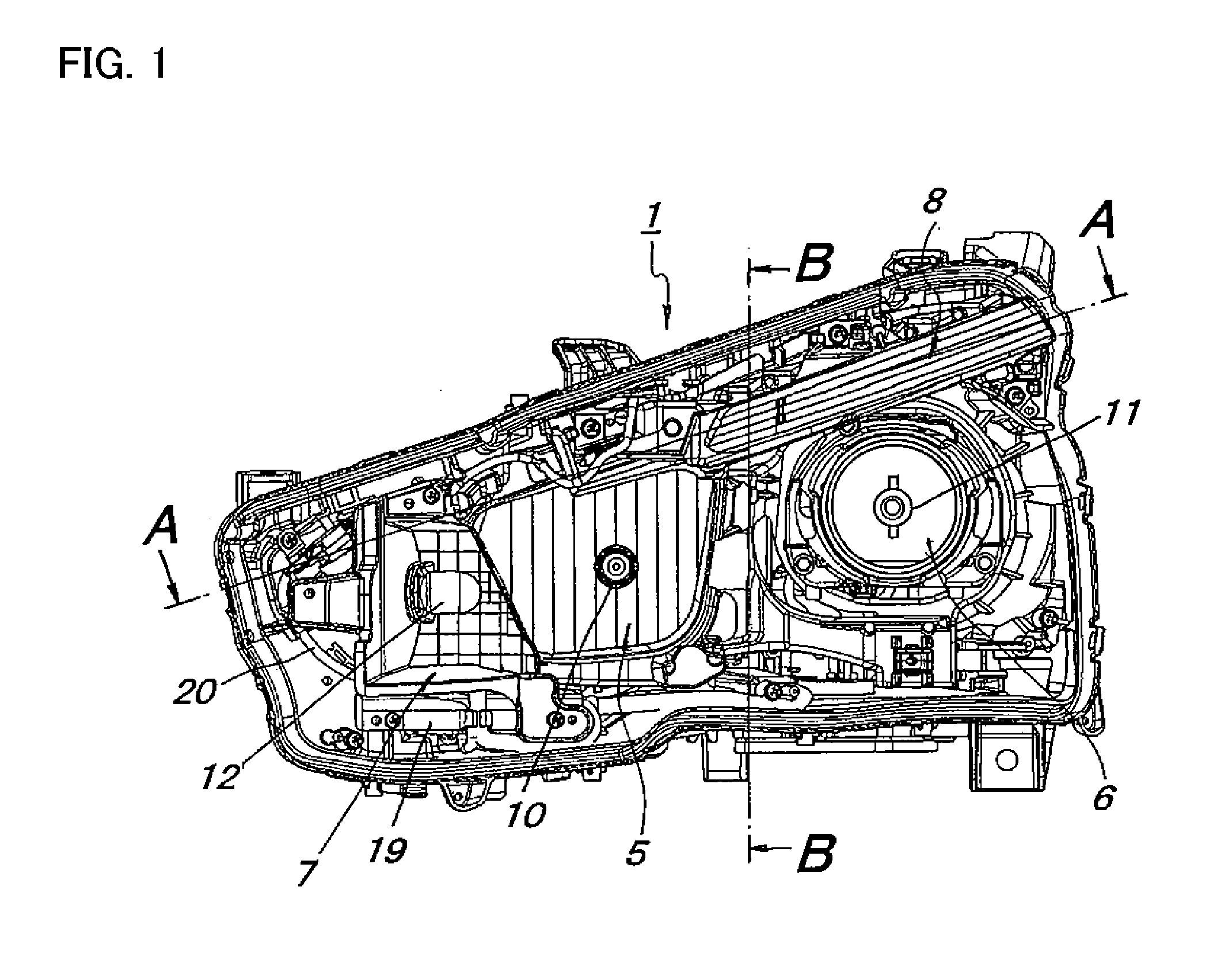
[0044]Exemplary embodiments of the disclosed subject matter will now be described in detail with reference to FIGS. 1 to 12. FIG. 1 is a front view showing an exemplary embodiment of a vehicle headlight made in accordance with principles of the disclosed subject matter, wherein a housing and an outer lens are not shown in FIG. 1 in order to facilitate a clear understanding of the disclosed subject matter.

[0045]A vehicle headlight 1 shown in FIG. 1 can be attached to a left front corner of a vehicle in a front view from the vehicle, and another vehicle headlight that is symmetrical to the vehicle headlight 1 can be attached to a right front corner of the vehicle. Accordingly, the vehicle headlight 1 will be described in the embodiment, and descriptions of the other vehicle headlight are abbreviated.

[0046]The vehicle headlight 1 can include: a high beam headlight 5 provided with a high beam light source 10 and being located in a middle portion thereof; a low beam headlight 6 provided ...


PUM


Abstract

A vehicle position lamp can include a plurality of circuit boards each mounting an LED. The vehicle position lamp can also include a first inner lens having a plurality of optical plates and at least one connecting plate connecting between the adjacent optical plates and a second inner lens. An inner surface of each of the optical plates can be located adjacent the respective one of the circuit boards so that an optical axis of a diffusing lens of each of the optical plates corresponds to a substantially optical axis of each of the LEDs. The second inner lens can be located adjacent the first inner lens that can be formed in various slender curved shapes. Thus, the disclosed subject matter can provide vehicle position lamps having a high visibility that are formed in various slender curved shapes such that match headlights, which fit both front corners of a vehicle.

Description

[0001]This application claims the priority benefit under 35 U.S.C. §119 of Japanese Patent Application No. 2011-013247 filed on Jan. 25, 2011, which is hereby incorporated in its entirety by reference.BACKGROUND[0002]1. Field[0003]The presently disclosed subject matter relates to vehicle position lamps using a plurality of LEDs and vehicle headlights using the position lamp, and more particularly to vehicle position lamps having a high visibility and a favorable light distribution, which can be incorporated into vehicle headlights along both front corners of a vehicle, and the vehicle headlights using the position lamps having a high visual quality, which can emit harmonious light with respect to each other.[0004]2. Description of the Related Art[0005]Various vehicle lamps incorporating a plurality of LEDs have became popular for vehicle signal lamps such as a stop lamp, a tail lamp and the like, because LEDs are battery friendly (lower power requirements), have long life, and are g...

Claims


Application Information

Patent Timeline
IPC IPC(8): F21V5/04
CPCF21S48/215F21S48/2206F21S48/2212F21S43/14F21S43/27F21S43/26
Inventor SASAKI, YOSHIHIROTOYOYAMA, HIDEKI
Owner STANLEY ELECTRIC CO LTD
Learn More