
Turbocharged reciprocating piston engine having a connected pressure tank for bridging turbo lag, and method for operating said engine

a reciprocating piston, turbocharged technology, applied in the direction of engine starters, machines/engines, electric control, etc., can solve the problems of high hurdles, and achieve the effect of reducing the cubic capacity

Inactive Publication Date: 2012-07-26
ETH ZZURICH
View PDF3 Cites 30 Cited by
  • Summary
  • Abstract
  • Description
  • Claims
  • Application Information

AI Technical Summary

Benefits of technology

[0017]The invention aims at the most important advantage of the pneumatic hybridization of reciprocating piston engines, which advantage has already been described above: the substantial reduction of the cubic capacity of a reciprocating piston engine with retention of the nominal power output with the aid of a turbocharger, as a result of the bridging of the turbo lag by means of compressed air which is introduced directly into a combustion chamber.
[0020]Various activation mechanisms on the basis of camshaft systems are inexpensive and are used in production vehicles. The “supercharged” mode similar to EP07018673.9 and FR2865769A1 can thus be made possible. This inexpensive configuration makes bridging of the turbo lag possible in a supercharged engine. All further embodiments are based on this configuration.

Problems solved by technology

High variability of actuating systems of valves represents a high hurdle for car manufacturers, since complexity and therefore costs rise in comparison with a conventional reciprocating piston engine.

Method used


Image

  • Turbocharged reciprocating piston engine having a connected pressure tank for bridging turbo lag, and method for operating said engine
  • Turbocharged reciprocating piston engine having a connected pressure tank for bridging turbo lag, and method for operating said engine
  • Turbocharged reciprocating piston engine having a connected pressure tank for bridging turbo lag, and method for operating said engine

Examples


embodiment 1 (fig.3)

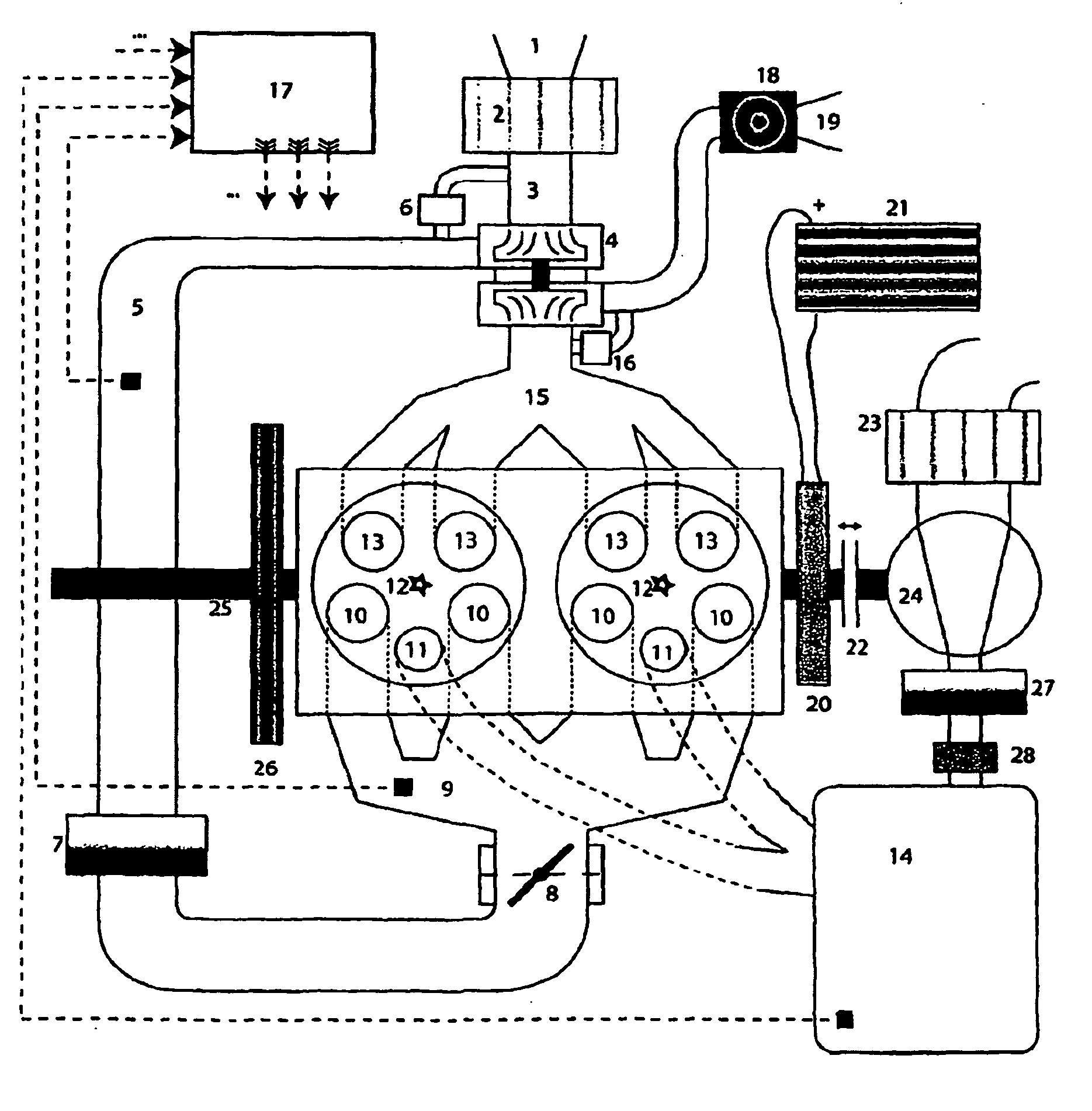
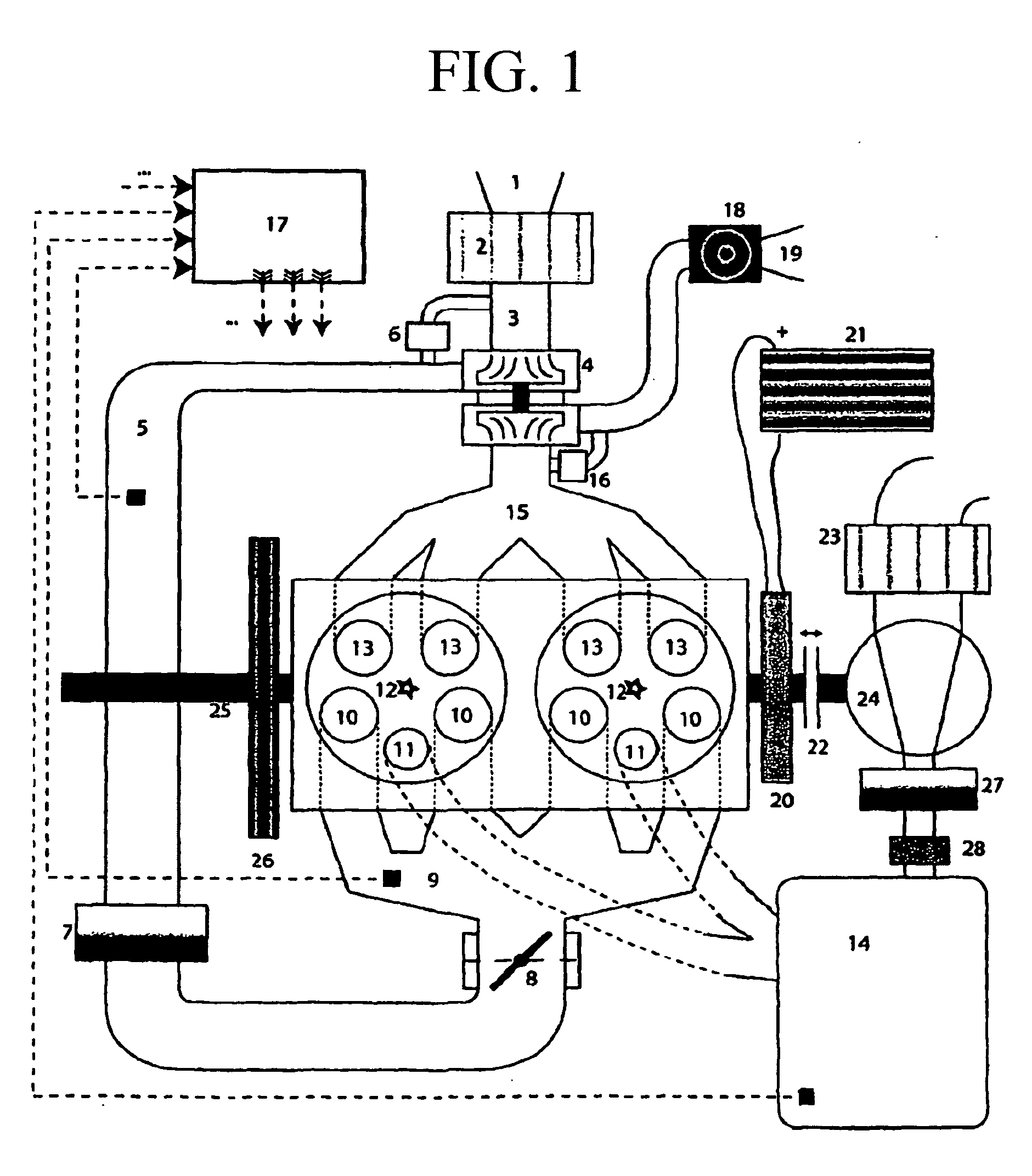
[0031]Embodiment 1 (FIG. 3): the air path runs as follows: the air is sucked in from the surroundings (1) and is cleaned by an air filter (2). The fluid-dynamic compressor of the turbocharger (4) compresses the air and delivers it into the next volume in the air path (5). If the pressure ratio between the volume (5) and that in front of the compressor (3) is too great (which is calculated with consideration of the air mass flow through the compressor), the wastegate valve (6) is used to guide a defined air mass flow back to the volume (3), said wastegate valve either functioning mechanically (as a function of the pressure difference), or else preferably being actuated electronically via the engine control unit (17). The air which is compressed by the compressor is cooled with the aid of a charge air cooler (air / water or air / air), in order to increase the density of the compressed air. The cooled air is throttled by an electronically or electromechanically actuable throttle valve (8)...

embodiment 2 (fig.4)

[0032]Embodiment 2 (FIG. 4): this embodiment differs from embodiment 1 merely in terms of the variability of the charging valve actuation. Here, the mechanical connection of the charging valves and the camshafts which actuate the charging valves can not only be deactivated, but rather the lift profile of the charging valves can be changed in such a way that the maximum stroke of the charging valves and the stroke duration (in relation to the crank angle difference) can be changed. This can be realized by way of mass production compatible technologies such as Valvetronic from the company BMW AG. The opening instant of the charging valves preferably remains unchanged. This embodiment permits more precise control of the air mass which is situated in the combustion chamber before initiation of the combustion.

[0033]Embodiment 3 (FIG. 5): this embodiment differs from embodiment 1 in terms of the variability of the charging valve control and the omission of the external compressor (24) and...


PUM


Abstract

The present invention relates to a turbo-charged reciprocating piston engine having a combustion chamber, and to a method for operating said engine. The combustion chamber has at least one inlet valve (10), one outlet valve (13) and at least one additional charging valve (11), for the additional feed of compressed air to bridge the turbo lag. All the valves (10, 11, 13) are operatively connected to the crankshaft via a camshaft and the operative connection of the charging valves to the crankshaft can be deactivated, with the result that the at least one charging valve (11) remains closed. The correct metering of the air for a stoichiometric or approximately stoichiometric combustion mixture is additionally achieved by a turbocharger (4) and a throttle valve (8). By displacement of the opening instant of the charging valves (11), air can be pumped from the cylindrical combustion chambers into the compressed air tank (14), instead of removing said air from the latter. Furthermore, an additional compressor (24), driven by the crankshaft, can likewise deliver air into the compressed air tank (14) if required.

Description

BACKGROUND OF THE INVENTION[0001]1. Field of the Invention[0002]The present invention relates to an improved supercharged internal combustion engine which operates using the four stroke cycle and has a compressed air tank for the purpose of bridging turbo lag.[0003]2. Discussion of Related Art[0004]Reciprocating piston engines were invented more than 100 years ago and have been developed continuously since then, but their maximum degree of efficiency is subject to thermodynamic limits. If a reciprocating piston machine were operated constantly at its maximum degree of efficiency, approximately only half as much fuel would have been burned worldwide as is actually the case today. The main reason for the inefficient utilization of contemporary reciprocating piston engines is that the engine is usually operated only at part load (city traffic, constant speeds, . . . ), where the degrees of efficiency are poor. Since car drivers demand vehicles with a high maximum performance, the resul...

Claims


Application Information

Patent Timeline
Patent Type & Authority Applications(United States)
IPC IPC(8): F02B37/10F02B33/00
CPCF02B21/00Y02T10/18F02B33/34F02B37/007F02B37/04F02B37/127F02B37/16F02B37/18F02B39/04F02B39/12F02D13/0276F02D35/023F02D41/0007F02M2023/008F02N11/04Y02T10/146Y02T10/144F02B29/00F02B37/162Y02T10/12
Inventor GUZZELLA, LINODONITZ, CHRISTIANONDER, CHRISTOPHER H.VOSER, CHRISTOPH
Owner ETH ZZURICH
Learn More