
Heat pump system having a pre-processing module

a heat pump and pre-processing technology, applied in the field of heat pump systems, can solve the problems of reducing the efficiency of the regeneration air heat exchanger, the disadvantages of conventional heat pump systems,

Active Publication Date: 2012-07-19
NORTEK AIR SOLUTIONS CANADA INC
View PDF3 Cites 66 Cited by
  • Summary
  • Abstract
  • Description
  • Claims
  • Application Information

AI Technical Summary

Benefits of technology

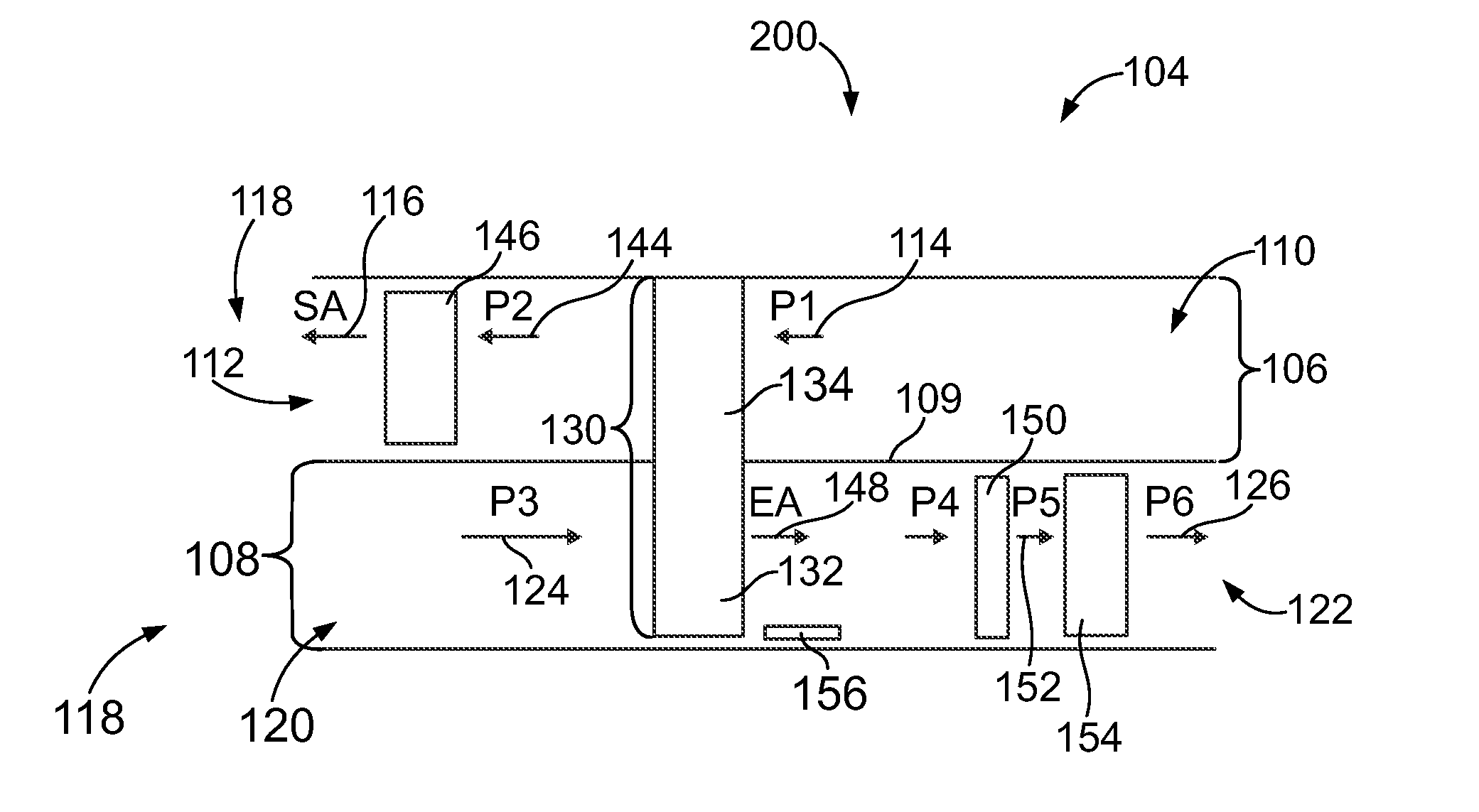
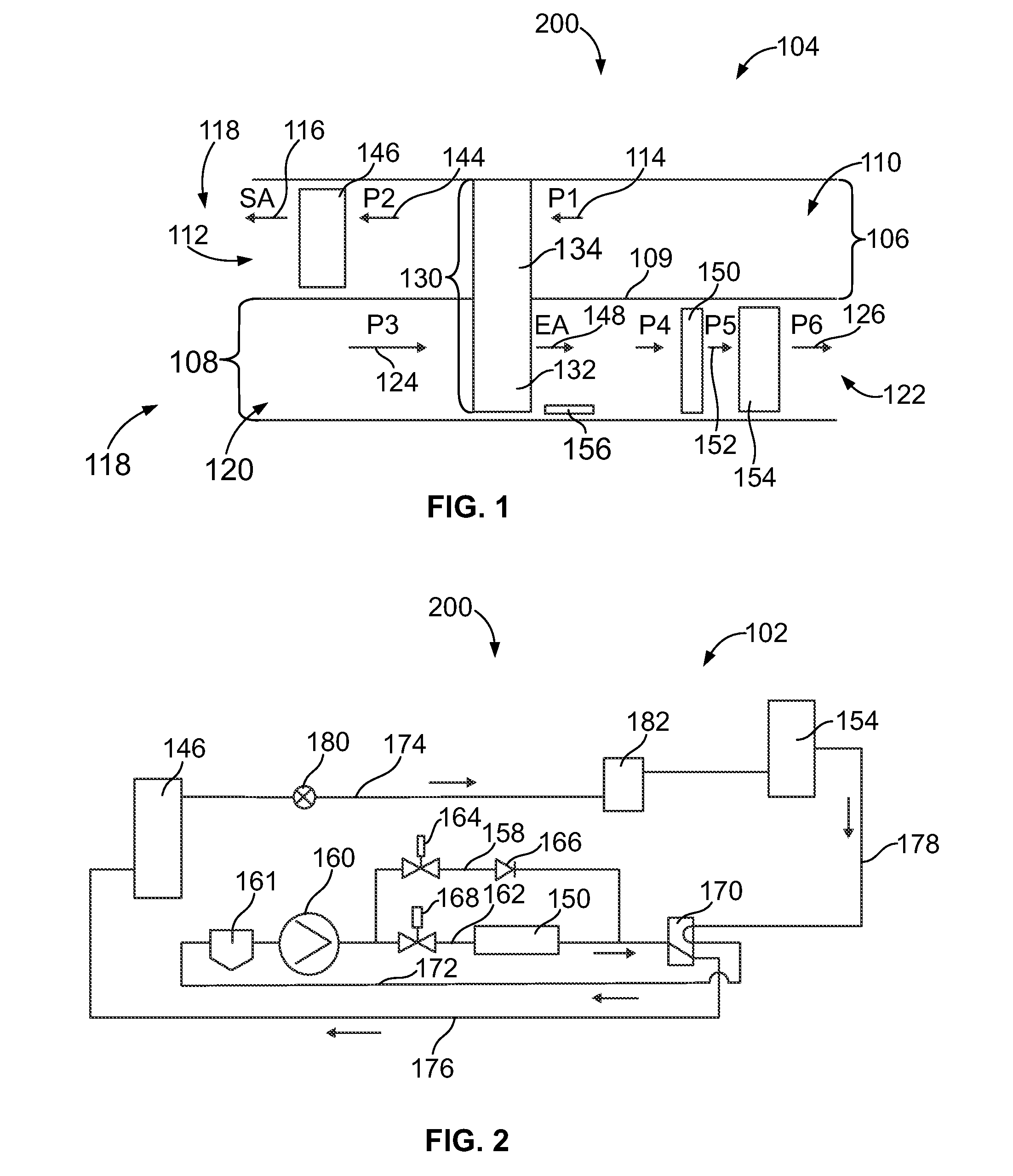
[0006]In one embodiment, a heat pump system for conditioning air in a space is provided. The system includes a supply air channel to receive outside air and discharge supply air into a space. A regeneration air channel is provided to receive regeneration air from the space and discharge exhaust air. The regeneration air channel and the supply air channel are separated by a partition. An energy recovery module is provided having a supply air side positioned in the supply air channel and a regeneration air side positioned in the regeneration air channel. The regeneration air side of the energy recovery module removes heat and moisture from the regeneration air in the regeneration air channel in a winter mode. A regeneration air heat exchanger is positioned in the regeneration air channel downstream from the regeneration air side of the energy recovery module. The regeneration air heat exchanger removes heat from the regeneration air in the winter mode. The regeneration air heat exchanger discharges the exhaust air. A pre-processing module is positioned in the regeneration air channel between the regeneration air side of the energy recovery module and the regeneration air heat exchanger. The pre-processing module heats the regeneration air from the energy recovery module in the winter mode to prevent frost from forming on the regeneration air heat exchanger.
[0007]In another embodiment, a heat pump system for conditioning air in a space is provided. The system comprising a supply air channel to receive outside air and discharge supply air into a space. A regeneration air channel is provided to receive regeneration air from the space and discharge exhaust air. The regeneration air channel and the supply air channel are separated by a partition. An energy recovery module is provided having a supply air side positioned in the supply air channel and a regeneration air side positioned in the regeneration air channel. The regeneration air side of the energy recovery module heats and humidifies the regeneration air in the regeneration air channel in a summer mode. A regeneration air heat exchanger is positioned in the regeneration air channel downstream from the regeneration air side of the energy recovery module. The regeneration air heat exchanger heats the regeneration air in the summer mode. The regeneration air heat exchanger discharges the exhaust air. A pre-processing module is positioned in the regeneration air channel between the regeneration air side of the energy recovery module and the regeneration air heat exchanger. The pre-processing module heats the regeneration air from the energy recovery module in the summer mode to lower a condensation temperature and increase an efficiency of the regeneration air heat exchanger.
[0013]At least one recirculation damper is positioned within the partition. The at least one recirculation damper is configured to be opened during a defrost cycle to provide a recirculation loop of regeneration air that recirculates through a defrost airflow path defined by at least a portion of a pre-processing segment of the supply air channel and at least a portion of a downstream segment of the regeneration air channel. The recirculation loop of exhaust air removes frost from the regeneration air heat exchanger during the defrost cycle.
[0019]The heat pump system may also include a pre-processing module positioned in the regeneration air channel between the regeneration air side of the energy recovery module and the regeneration air heat exchanger. The pre-processing module is configured to heat the regeneration air from the energy recovery module during the heating cycle to prevent frost from forming on the regeneration air heat exchanger.
[0024]Certain embodiments provide a method of preventing frost from forming on a regeneration air heat exchanger within a regeneration air channel of a heat pump system. The method may include deactivating supply and exhaust fans positioned within supply air and regeneration air channels, respectively, closing inlet and outlet dampers disposed within the supply air and regeneration air channels, respectively, opening recirculation dampers disposed within a partition that separates the supply air and regeneration air channels, and recirculating a loop of regeneration air between the supply air and regeneration air channels, wherein the loop of regeneration air removes frost from the regeneration air heat exchanger.
[0028]Certain embodiments provide a method of operating a heat pump system to heat a space and defrost a regeneration air heat exchanger disposed within a regeneration air channel. The method may include operating the heat pump system in a heating cycle for a first period of time, transitioning the heat pump system from the heating cycle to a defrost cycle after the first period of time, operating the heat pump system in the defrost cycle for a second period of time, and preventing frost from forming on the regeneration air heat exchanger through the operating the heat pump system in the defrost cycle for the second period of time. The method may also include transitioning the heat pump system back to the heating cycle after the second period of time.

Problems solved by technology

However, conventional heat pump systems are not without their disadvantages.
Additionally, during summer modes, the regeneration air heat exchanger may be required to supply large amounts of heat to the regeneration air.
As a result, an efficiency of the regeneration air heat exchanger may decrease substantially.

Method used


Image

  • Heat pump system having a pre-processing module
  • Heat pump system having a pre-processing module
  • Heat pump system having a pre-processing module

Examples


Embodiment Construction

[0041]The foregoing summary, as well as the following detailed description of certain embodiments will be better understood when read in conjunction with the appended drawings. As used herein, an element or step recited in the singular and proceeded with the word“a” or “an” should be understood as not excluding plural of said elements or steps, unless such exclusion is explicitly stated. Furthermore, references to “one embodiment” are not intended to be interpreted as excluding the existence of additional embodiments that also incorporate the recited features. Moreover, unless explicitly stated to the contrary, embodiments “comprising” or “having” an element or a plurality of elements having a particular property may include additional such elements not having that property.

[0042]FIG. 1 is a schematic diagram of a heat pump system 104 formed in accordance with an embodiment and operating in a winter mode 200. The heat pump system 104 is in fluid communication with a refrigerant syst...


PUM


Abstract

A heat pump system is operable in winter mode and / or summer mode, and may be selectively operated in a defrost mode or cycle. The system includes an energy recovery module that receives and conditions air in a regeneration air channel. A pre-processing module is positioned downstream of the energy recovery module. The pre-processing module receives and heats air from the energy recovery module. A regeneration air heat exchanger is positioned downstream of the pre-processing module. The regeneration air heat exchanger receives and conditions air from the pre-processing module. The pre-processing module heats the air from the energy recovery module to increase efficiency of the regeneration air heat exchanger. During the defrost mode, a loop of regeneration air may be recirculated between the supply air channel and the regeneration air channel in order to defrost the regeneration air heat exchanger.

Description

CROSS-REFERENCE TO RELATED APPLICATIONS[0001]The present application is a continuation-in-part of U.S. patent application Ser. No. 13 / 009,222 entitled “Heat Pump System Having a Pre-Processing Module” filed Jan. 19, 2011, the complete subject matter of which is hereby expressly incorporated by reference in its entirety.BACKGROUND OF THE INVENTION[0002]The subject matter described herein relates to a heat pump system and, more particularly, to a heat pump system for low temperature operation.[0003]Existing air-to-air heat pumps generally include a supply air channel and a regeneration air channel. An energy exchange module extends between the supply air channel and the regeneration air channel. The energy exchange module transfers sensible and / or latent heat between the outside air in the supply air channel and the regeneration air in the regeneration air channel. The supply air channel and the regeneration air channel also include heat exchangers. The supply air channel includes a s...

Claims


Application Information

Patent Timeline
Patent Type & Authority Applications(United States)
IPC IPC(8): F25D21/12F25D21/04
CPCY02B30/126F25B13/00F25B40/04F25B2313/021F25B2313/02741F25B2400/0405F24D19/0095F25B2600/2517Y02B30/52F24D5/12F24F12/00F24F2011/0087F25B2600/2501F24F12/003F24F11/42Y02B30/13Y02B30/56Y02B30/12
Inventor GERBER, MANFREDRONG, CAN WEN
Owner NORTEK AIR SOLUTIONS CANADA INC
Learn More