
Corona igniter including ignition coil with improved isolation

a technology of ignition coil and ignition coil, which is applied in the manufacture of sparking plugs, sparking plugs, lighting and heating apparatus, etc., can solve the problems of parasitic energy loss, difficult to contain the high frequency and high voltage used in the corona ignition system, and the leakage of energy through the housing of the ignition coil, etc., to achieve less parasitic energy loss, less input power, and higher voltage and power

Inactive Publication Date: 2012-07-12
FEDERAL MOGUL IGNITION
View PDF1 Cites 18 Cited by
  • Summary
  • Abstract
  • Description
  • Claims
  • Application Information

AI Technical Summary

Benefits of technology

[0010]The coil filler and the capacitance reducing component electrically isolates the coil in the housing and thus creates less parasitic loss of energy from the coil during operation of the internal combustion engine compared to the corona igniters of the prior art with housings filled completely with a resin. The igniter requires less input power and outputs energy at a higher voltage and power due to less leakage of the energy through the housing. The improved insulation scheme provides improved energy efficiency with typically 30 to 50% less energy required compared to isolation schemes of the prior art corona igniters.

Problems solved by technology

The high frequency and high voltage used in the corona ignition system is difficult to contain, and leakage of energy through the housing of the ignition coil is a problem.
Conventional isolation techniques, for example encapsulation with resin, such as epoxy resin, add significantly to the capacitance of the system and cause a parasitic energy loss.
The pressurized gas maintains low parasitic energy loss but is difficult to execute with reliable stability and provides no mechanical support.
However, the completely resin filled housing leads to high parasitic energy loss and parasitic capacitance due to the high permittivity of the resin.

Method used


Image

  • Corona igniter including ignition coil with improved isolation
  • Corona igniter including ignition coil with improved isolation
  • Corona igniter including ignition coil with improved isolation

Examples


Embodiment Construction

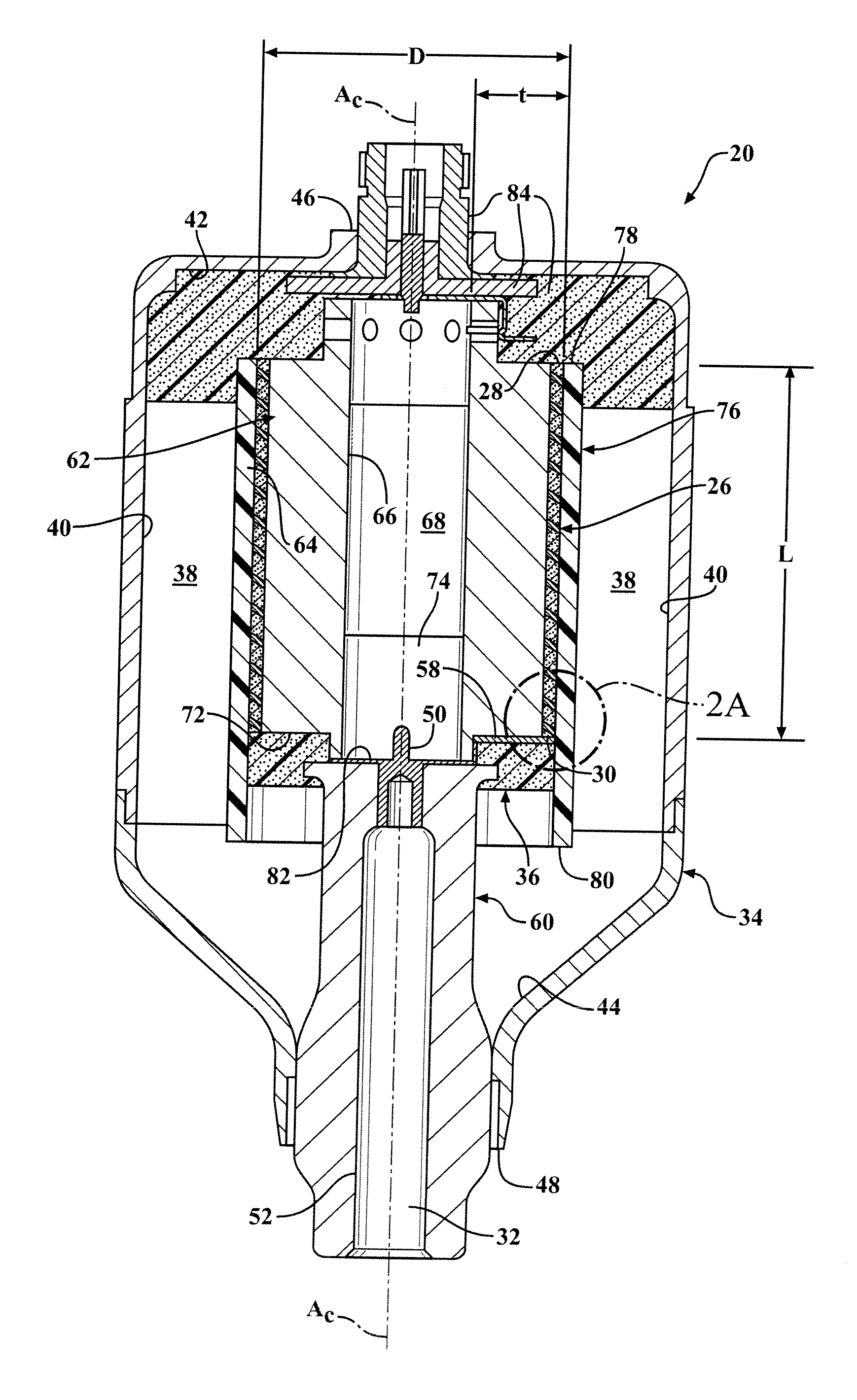
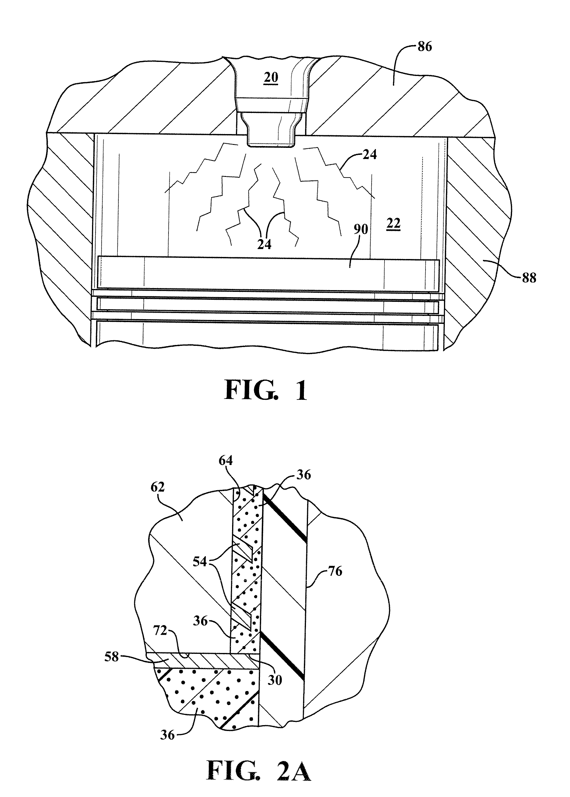
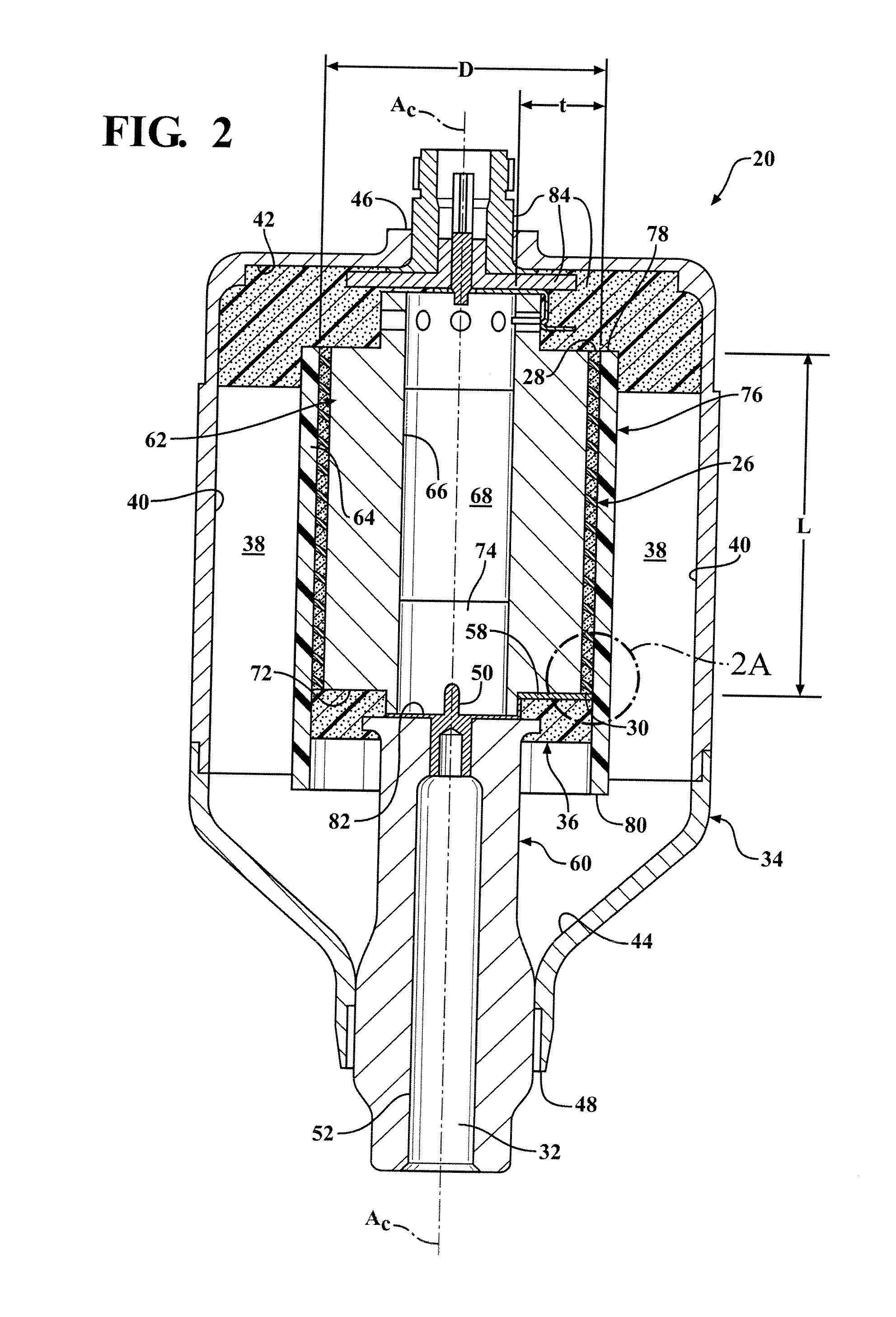
[0022]One aspect of the invention provides a corona ignition system including an igniter 20, as shown in FIG. 1. The corona igniter 20 is disposed in a combustion chamber 22 and emits a radio frequency electric field to ionize a portion of a fuel-air mixture and provide a corona discharge 24 in the combustion chamber 22. The igniter 20 includes an ignition coil 26, as shown in FIG. 2, receiving energy at a coil low voltage end 28 from a power source (not shown) and transmitting the energy at a higher voltage from a coil high voltage end 30 to an electrode (not shown). Improved isolation of the ignition coil 26 is provided in a housing 34 of the coil 26. A minimal amount of a coil filler 36, such as a resin material, is coupled to the coil 26 and a capacitance reducing component 38, such as a pressurized gas, ambient air, insulating oil, or low permittivity solid fills the housing 34 around the coil 26. The coil filler 36 together with the capacitance reducing component 38 provide ex...


PUM


Abstract

A corona igniter (20) includes an ignition coil (26) providing a high voltage energy to an electrode. The coil (26) is disposed in a housing (34) and electrically isolated by a coil filler (36) and a capacitance reducing component (38) which together improve energy efficiency of the system. The coil filler (36) includes an insulating resin permeating the coil (26). The capacitance reducing component (38) has a permittivity not greater than 6, for example ambient air, pressurized gas, insulating oil, or a low permittivity solid. The capacitance reducing compound (38) surrounds the coil (26) and other components and fills the remaining housing volume. The coil filler (36) has a filler volume and the capacitance reducing component (38) has a component volume greater than the filler volume.

Description

CROSS REFERENCE TO RELATED APPLICATION[0001]This application claims the benefit of U.S. provisional application Ser. No. 61 / 423,306, filed Dec. 15, 2010.BACKGROUND OF THE INVENTION[0002]1. Field of the Invention[0003]This invention relates generally to a corona igniter for emitting a non-thermal plasma, and more specifically to isolation of an ignition coil of the corona igniter.[0004]2. Related Art[0005]An example of a corona discharge ignition system is disclosed in U.S. Pat. No. 6,883,507 to Freen. The corona discharge ignition system includes an igniter with an electrode charged to a high radio frequency voltage potential. An ignition coil housed in the igniter receives energy from a power source at a first voltage and transmits the energy to the electrode at a second voltage, typically 15 to 50 times higher than the first voltage. The electrode then creates a strong radio frequency electric field causing a portion of a mixture of fuel and air in the combustion chamber to ionize...

Claims


Application Information

Patent Timeline
Patent Type & Authority Applications(United States)
IPC IPC(8): H01T13/44H01T21/02
CPCH01T13/50H01T21/02F02P23/04H01F27/321H01F38/12H01F2038/122H01F2038/125H01F27/327H01F27/34H01T13/44
Inventor BURROWS, JOHN ANTONYLYKOWSKI, JAMES D.
Owner FEDERAL MOGUL IGNITION
Learn More