
Frame of jaw crusher, jaw crusher and crushing plant

a jaw crusher and frame technology, applied in the field of frame of a jaw crusher, a jaw crusher and a crushing plant, can solve the problems of reducing the fatigue strength of the side plates and the ends, the computational difficulty and laboriousness of controlling the fretting phenomenon, and the weight of the frame parts in the manufacture of pieces is moderate, and the amount of frame parts of the crusher may be considerably reduced.

Active Publication Date: 2012-07-12
METSO MINERALS INC
View PDF11 Cites 3 Cited by
  • Summary
  • Abstract
  • Description
  • Claims
  • Application Information

AI Technical Summary

Benefits of technology

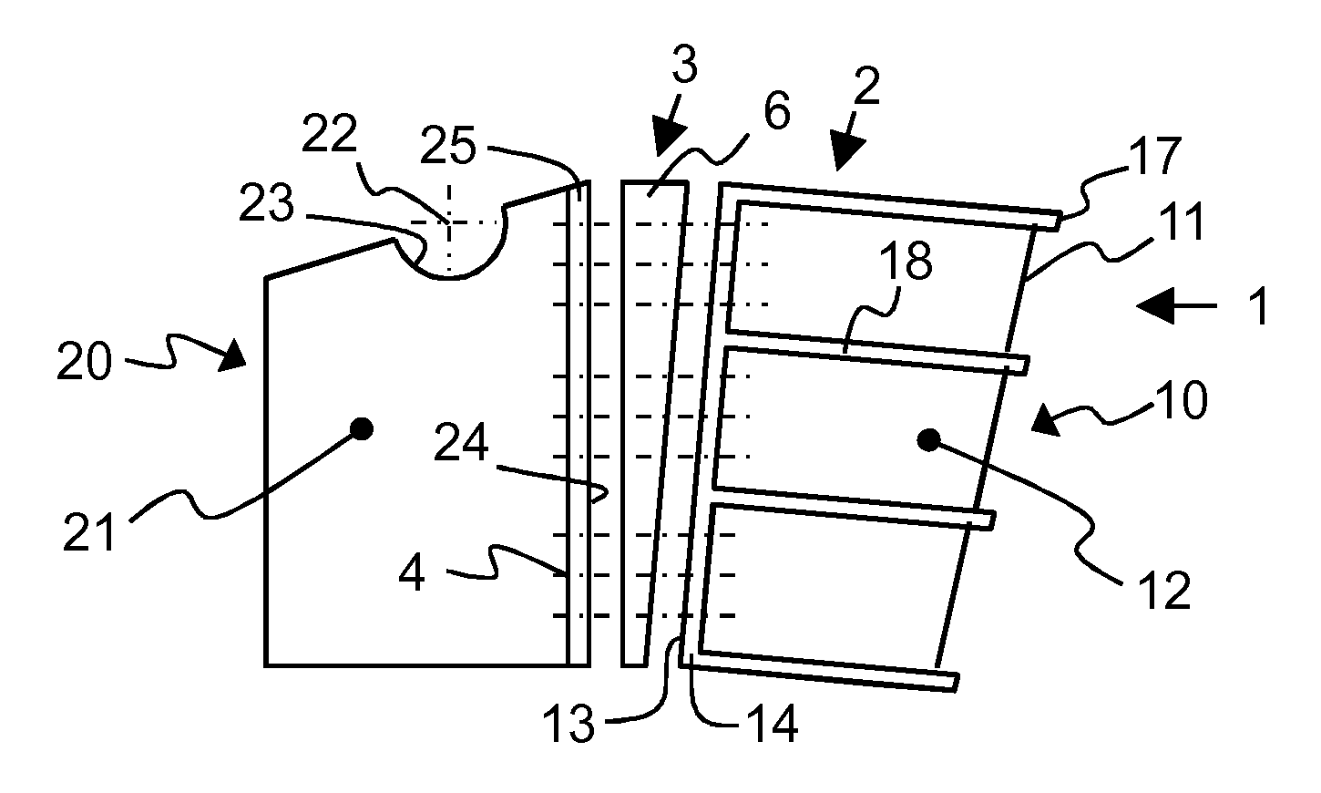
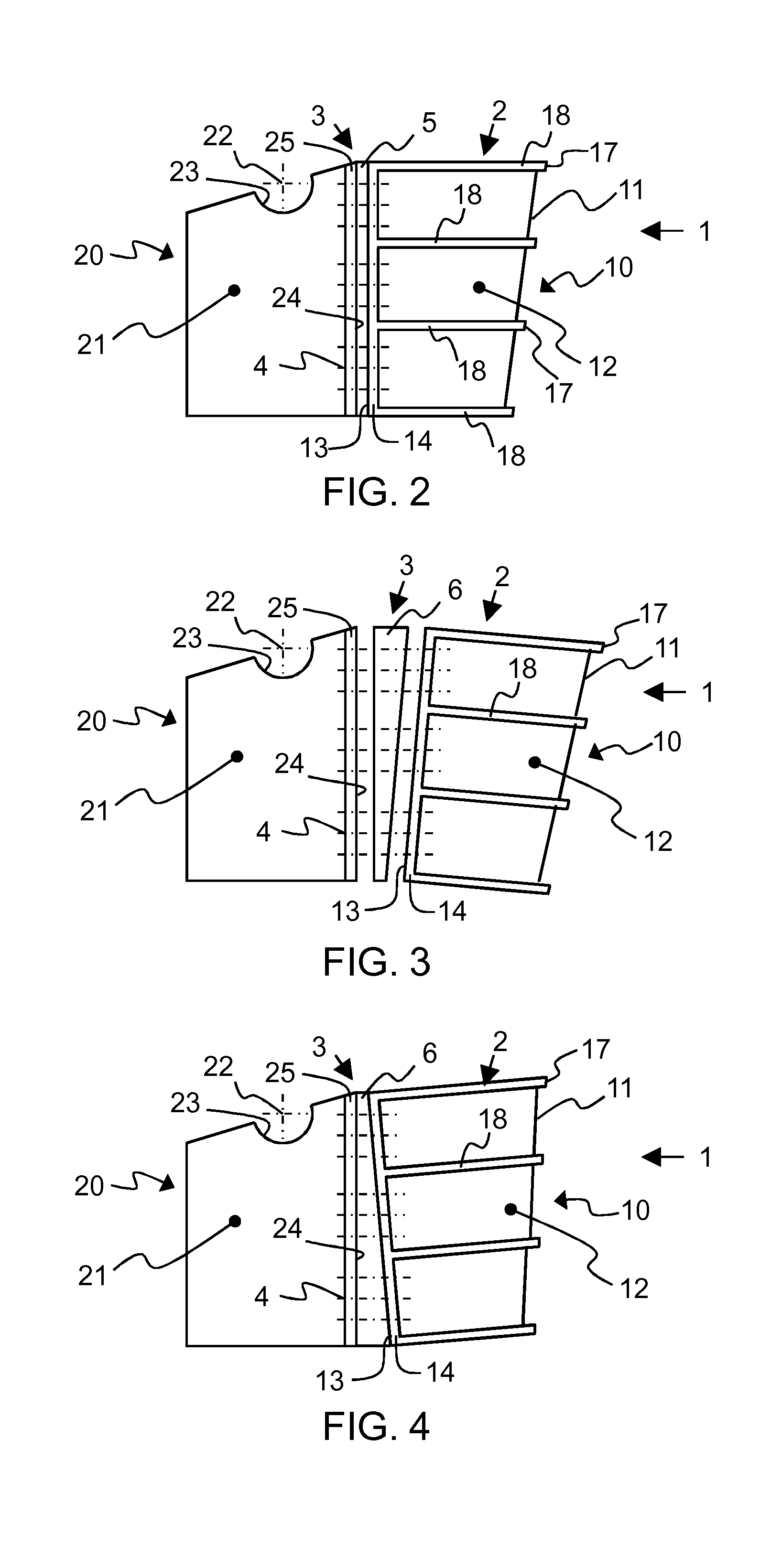
[0028]The frame of a crusher assembled of two, frame parts which frame's front part is manufactured by casting has many advantages. Joints proven to be problematic between load transferring large frame pieces are less needed, and the weight of frame parts handled in the manufacture of pieces is held moderate. Because the casting of the frame may be realized in two parts the casting may be made simpler than of one big part. For smaller parts there are several alternative places for making the actual casting work.
[0029]The amount of frame parts of the crusher may be considerably decreased when compared to a frame which comprises side plates and ends which are assembled to each other with bolt joints. The amount of machined surface may be considered as small in the preferred embodiments of the present invention. The weight of the frame may be decreased even with a fifth when compared to frames equipped with extending pins and joined with bolt joints.
[0030]In some embodiments of the frame of the jaw crusher the after-tightening problem of bolts may be considerably avoided. In some embodiments of the frame of the jaw crusher fretting fatigue problems are eliminated.
[0031]A fork-pin joint may be gotten gapless. Because the joint may be placed in the middle area of the side walls of the frame half of the amount of pins of some solutions is needed in which solutions side plates and ends are assembled to each other with bolt joints. In some embodiments of the present invention the pin may be considered as a beam with two supports and not as a cantilever beam according to known steel cast pins wherein the pin may be dimensioned by its diameter considerably smaller than known pins. In that case the hole for fork-pin joint formed in the casting material of the frame may be formed small so that the stress concentration in the area of the pin hole may be gotten low. In question is a situation defined to be dimensionally static wherein the pins, the fork eye and the tongue may be analytically dimensioned to correspond the load of the crushing event. The amount of fatigue critical places of joints of the frame may be decreased and the influence of friction may be considered to be small. Pin joints are easy to mount. Pins may be replaced easily.

Problems solved by technology

The movement between friction surfaces of the bolt joints exposes joints to loosening and / or fretting fatigue that decreases considerably fatigue strength of the side plates and the ends.
Fretting fatigue is a very serious form of fatigue because it may also occur in such areas which are not critical regarding to stress.
Controlling the fretting phenomenon is computationally difficult and laborious because influences of friction, such as friction coefficient, in joints are not accurately known.
Extending pins receiving shear forces of present multipart frame assembled with bolts and casted to the ends of the frame cannot be replaced when the pins wear away.
In bolt joints, especially due to the large amount of frame bolts, lots of places critical to the fretting fatigue are caused to the frame because users easily forget after-tightening of frame bolts.
Lots of frame bolts and massive base plates used with the frame bolts and lots of extending pins are used in the multipart frame of a jaw crusher due to which expensive machined surface must be plentifully produced to the frame.
Thus, the amount of parts and expensive machining grows high that increases price and assembly time.
Very many critical fatigue vulnerable places are formed to a welded frame of a jaw crusher due to the high amount of welding seams, especially, if there are welding joints getting under stress in the area of the front wall subject to crushing load.
Quality assurance of the weldings in the welded frame increases costs.
Quality assurance in complex welded structures is difficult and expensive.
The intermediate piece is heavy and difficult to mount.
Relievings for decreasing weight have been made to the known adjustment plates of the jaw angle that increases manufacturing costs.

Method used


Image

  • Frame of jaw crusher, jaw crusher and crushing plant
  • Frame of jaw crusher, jaw crusher and crushing plant
  • Frame of jaw crusher, jaw crusher and crushing plant

Examples


Embodiment Construction

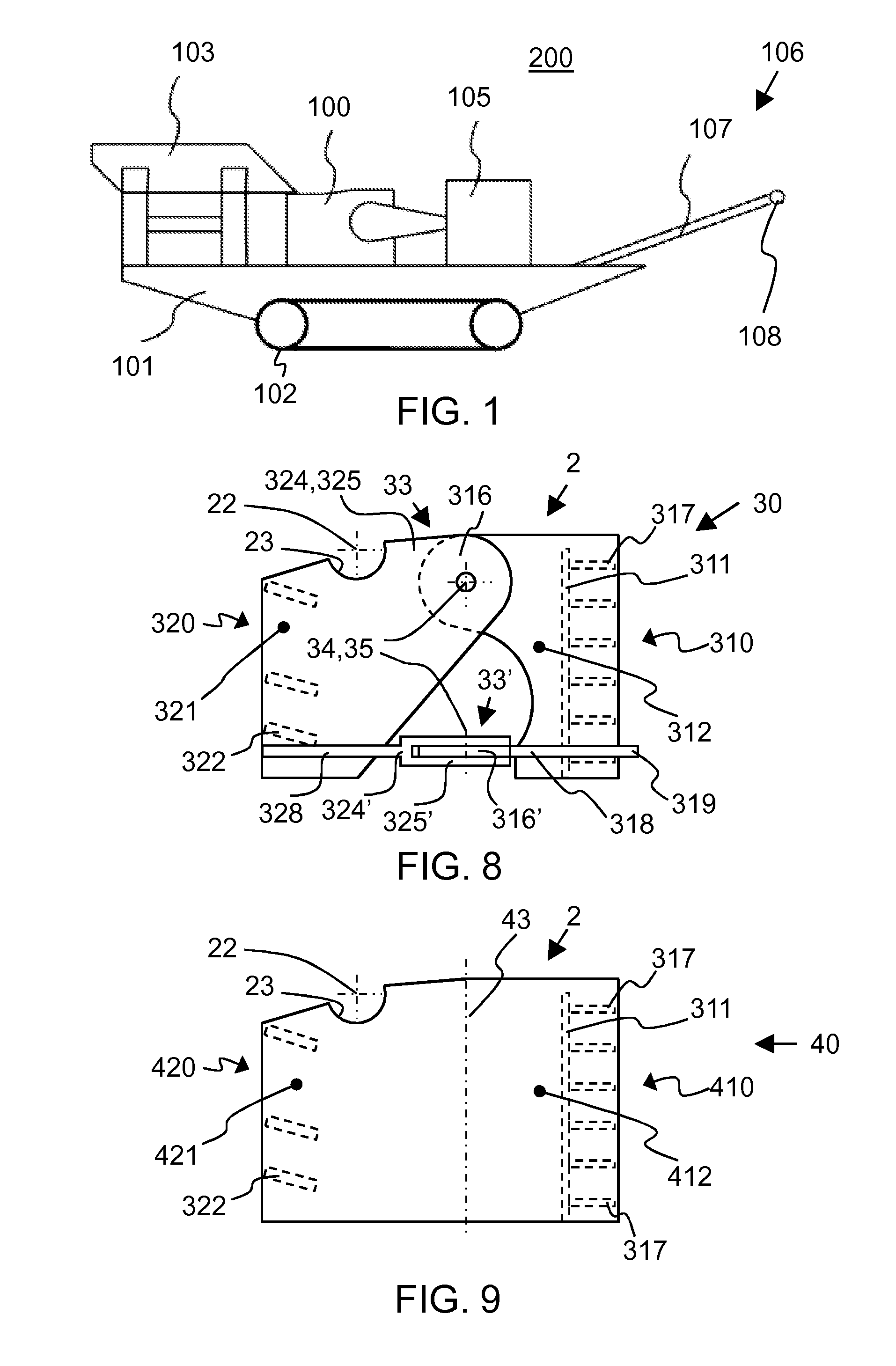
[0044]In the following description, like numbers denote like elements. It should be appreciated that the illustrated drawings are not entirely in scale, and that the drawings mainly serve the purpose of illustrating embodiments of the invention.

[0045]FIG. 1 shows a processing apparatus of mineral material, crushing plant 200 which comprises a jaw crusher 100. Crushing plant 200 has a feeder 103 for feeding material to the jaw crusher 100 and a belt conveyor 106 for conveying crushed product away off from the crushing plant.

[0046]The belt conveyor 106 presented in FIG. 1 comprises a belt 107 which is adapted to run at least around one drum 108. The crushing plant 200 also comprises a power source and a control center 105. The power source may be, for example, a diesel motor or an electric motor which offers energy for use of process units and hydraulic circuits.

[0047]The feeder 103, the crusher 100, power source 105 and conveyor 106 are attached to a frame 101 of the crushing plant w...


PUM


Abstract

A frame of a jaw crusher comprises a front wall for receiving crushing force and side walls connected to the front wall. The frame of the jaw crusher comprises a front part and a rear part joinable to the front part, and the front part comprises the front wall, and a major part of the front wall and the front part of both side walls form a unitary piece. A jaw crusher and a crushing plant.

Description

FIELD OF THE INVENTION[0001]The invention relates to a frame of a jaw crusher, a jaw crusher and a crushing plant which are suitable for crushing mineral material.BACKGROUND OF THE INVENTION[0002]Frames of jaw crushers have been manufactured in many different ways. One typical frame of a jaw crusher comprises side plates and ends which are assembled with bolt joints. A jaw crusher may also comprise a completely casted or a completely welded frame.[0003]Side plates of a jaw crusher are attached with bolt joints to, for example, casted ends in which shear forces created while loading the crusher are received with extending pins casted to the ends. The movement between friction surfaces of the bolt joints exposes joints to loosening and / or fretting fatigue that decreases considerably fatigue strength of the side plates and the ends. Due to the loosening frame bolts of the side plates attached to the ends require regular checking and when needed after-tightening.[0004]Initiation of a cr...

Claims


Application Information

Patent Timeline
Patent Type & Authority Applications(United States)
IPC IPC(8): B02C1/02
CPCB02C1/04B02C1/02B02C13/282B02C19/00B02C23/00B02C2018/162
Inventor SUTTI, RISTORIKKONEN, KARISOMERO, ILKKAHEIKKILA, JUHAMATTIJONKKA, JARIYLI-MARTTILA, MIKA
Owner METSO MINERALS INC
Learn More