
Reinforced therapeutic wrap and method

a technology of a therapeutic wrap and a reinforced surface, which is applied in the field of therapeutic wrap, can solve the problems of localized kinking or buckling in the bladder, inhibiting fluid flow and operation, and generally occurring kinking types, so as to increase the resistance to kinking of the fluid bladder

Active Publication Date: 2012-07-05
AVENT INC
View PDF5 Cites 35 Cited by
  • Summary
  • Abstract
  • Description
  • Claims
  • Application Information

AI Technical Summary

Benefits of technology

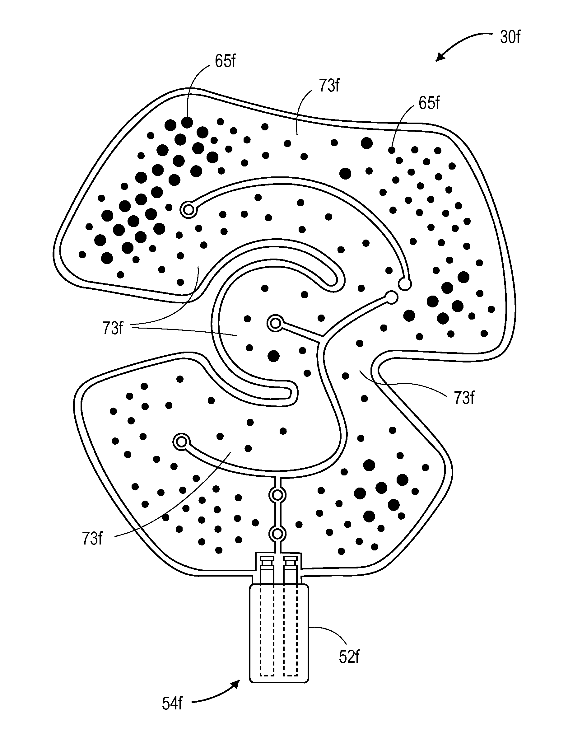
[0018]Various aspects of the invention are directed to a therapy wrap including a flexible fluid bladder for containing a heat exchange medium, the fluid bladder including an inlet, an outlet, a fluid flowpath connecting the inlet and the outlet, and a plurality of attachment points connecting walls of the bladder and defining a plurality of fluidic channels in the flowpath; and a gas pressure bladder for applying a compressive force to a portion of the fluid bladder in contact with the body part. The attachment points are positioned and dimensioned to increase resistance to kinking of the fluid bladder.
[0019]Various aspects of the invention are directed to a therapy wrap for providing heating or cooling to an anatomical body part, the wrap including a flexible fluid bladder for containing a heat exchange medium, the fluid bladder including an inlet, an outlet, a fluid flowpath connecting the inlet and the outlet, and a plurality of attachment points connecting walls of the bladder and defining a plurality of fluidic channels in the flowpath; and a gas pressure bladder overlaying the fluid bladder for applying a compressive force to a portion of the fluid bladder in contact with the body part. A portion of the plurality of attachment points may be positioned and dimensioned to increase resistance to kinking of the fluid bladder in a region of the fluid bladder prone to kinking during use.
[0032]In various embodiments, the wrap includes a selectively reinforced dot pattern to increase the local tensile strength by at least about 10%, and more preferably at least about 20%, at least about 50%, at least about 75%, at least about 100%, or at least about 150%. In various embodiments, the selectively reinforced dot pattern is configured to reduce the occurrence of kinking during use by at least about 10%, and more preferably at least about 20%, at least about 50%, or at least about 75%.
[0036]In various embodiments, the kink reducer comprises a discrete reinforcement member to impart significantly increased resistance to kinking in the kink-resistant zone relative to the remainder of the heat exchanger. In various embodiments, the kink reducer comprises a discrete reinforcement member coupled to the fluid bladder in the kink-resistant zone. In various embodiments, the reinforcement member increases the tensile bending strength of the kink-resistant zone by at least 75% relative to the remainder of the heat exchanger. In various embodiments, the reinforcement member increases the tensile bending strength of the kink-resistant zone by at least 25%, by at least 50%, or by at least 75% relative to the remainder of the heat exchanger. The reinforcement member may be a rigid body having a shape selected from a wire, an exoskeleton, a ribbon, and a sheet.
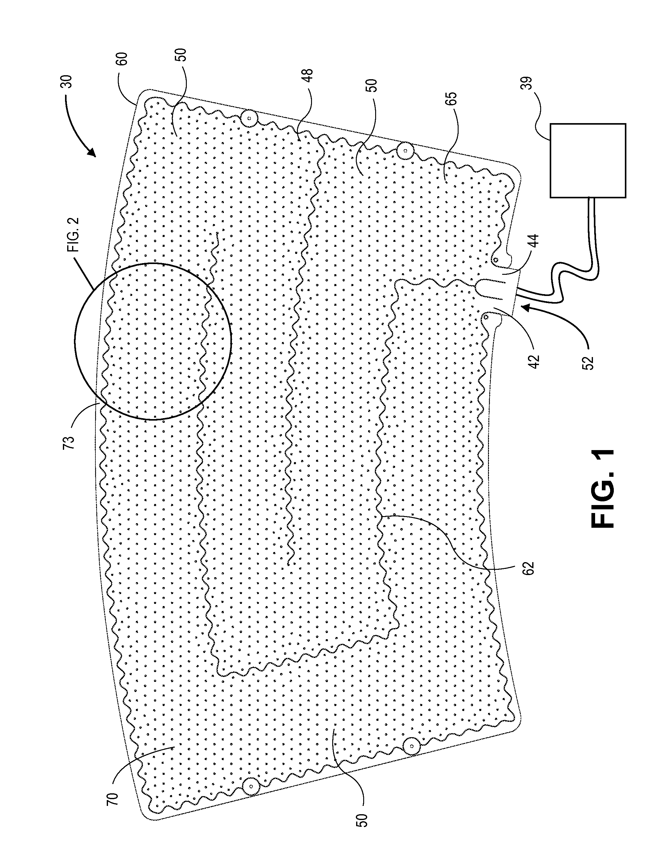
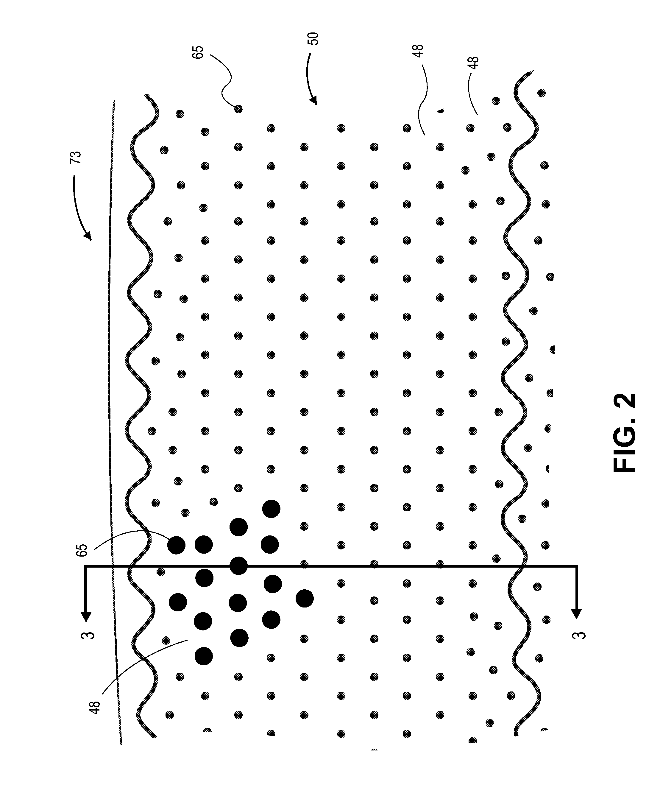
[0043]In various embodiments, a plurality of connections join the first and middle layers to form a fluid bladder. The plurality of connections may include dots and fences defining a plurality of fluidic channels in the fluid bladder. In various embodiments, the fluid bladder includes a first zone and a second zone of dots; the dots in the second zone increase a bending strength of the second zone relative to the first zone when the wrap is in use.

Problems solved by technology

A problem occurs when applying the wrap to such complex shapes.
Bending of the wrap in one or more directions can cause localized kinking or buckling in the bladder.
In some cases, one or more fluid pathways becomes crimped or completely occluded, thereby inhibiting fluid flow and operation.
This type of kinking generally occurs because of the inability of the material to conform to the complex shape of the anatomical part to which it is applied.
Kinking leads to several performance problems.
Kinking of the fluidic channels can lead to cool spots that are uncomfortable for the user and render heat transfer inconsistent.
Kinking can also undesirably increase backpressure in local regions of the fluid bladder.
To date, the effects of kinking in the context of therapy wraps have not been adequately explored.
The conventional use of dots is limited in that such fluid bladders experience an undesirably large number of kink failures and other failure modes during use, especially when applied to complex body parts and / or in compression from a pressure bladder.
Among the many limitations of this approach, increasing the rigidity of the materials detrimentally requires a trade-off between conformability of the wrap and kink resistance.
Even if a complete blockage of the fluidic channel does not occur, an undesirable reduction of fluid flow generally decreases wrap performance.

Method used


Image

  • Reinforced therapeutic wrap and method
  • Reinforced therapeutic wrap and method
  • Reinforced therapeutic wrap and method

Examples


example 1

[0224]A first wrap, referred to in some respects as the “first bladder” or the “reinforced bladder” and labeled as “Example A” in FIG. 12, was prepared similar to that shown in FIG. 1. The exemplary first wrap included a repeating equilateral triangle dot pattern forming fluidic channels. The center-to-center dot spacing, which corresponds to the widths of the fluidic channels, was about 0.425″. The dot diameters were between about 0.16″ and 0.2″.

[0225]The wrap was connected to a standard control unit and supplied with tap water from an ice bath reservoir at approximately 19 psi. The bladder was left in a flat condition in an ambient environment.

[0226]The bladder was then tested by displacing the fluid bladder with a 2″-diameter force plate in a kink-prone region. The force plate was applied to the bladder with a screw. The force applied by the bladder against the disk was measured at different levels of displacement, generally 0.010″-0.015″ increments. The disk force was increased ...

example 2

[0237]The same two fluid bladders were tested again under the same conditions except the fluid pressure was decreased to 10 psi. The results are shown in FIG. 13 where “Example A” refers to the same first bladder with reinforcement and “Example B” refers to the same second bladder without reinforcement, as described above.

[0238]Again, the results of this Example demonstrate that the force from the first bladder is generally higher at each given displacement level. In fact, as the displacement increases, the gap between the restoring force in the first bladder and the restoring force in the second bladder increases. Thus, the fluidic channels defined by the kink-resistant dot pattern in the first bladder are shown to provide increased resistance to kinking.

example 3

[0239]The same two wraps above were provided. A third wrap having a conventional dot pattern was provided. The three wraps were filled with tap water. The water volume in the wrap per surface area of the wrap was measured versus the pressure to fill the wrap. The results are shown in FIG. 14 where “Example A”, “Example B”, and “Example C” are the results for the three exemplary wraps.

[0240]The bladder of Example A corresponds to the first bladder with reinforcement described in Example 1 above. The bladder of Example B corresponds to the second, conventional bladder of Example 1 above. Example C was similar to Example B in terms of relative dot spacing but had larger fluid bladder. FIG. 14 shows how volume / surface area corresponds to pressure for the three wraps.

[0241]The results shown in FIG. 14 illustrate that a large fluid volume (Example C) is not functional at even moderate pressures, namely, above about 15 psi. Example C generally exhibited inferior performance at low pressure...


PUM

PropertyMeasurementUnit
Lengthaaaaaaaaaa
Lengthaaaaaaaaaa
Lengthaaaaaaaaaa

Abstract

A therapy wrap for treatment of at least a portion of an animate body having improved kink resistance. The therapy wrap may be selectively reinforced for improved kink resistance in only a portion of the wrap. The reinforcement may decrease the kink radius. The wrap may include a kink reducer in all or only a selected kink-prone region. The kink reducer may be selectively configured attachment points or spot welds. The therapy wrap may include a reinforcement layer of one or more discrete reinforcement members. The wrap may be formed by pre-tensioning the material layers while forming the fluid bladder and / or gas pressure bladder. The therapy wrap may be adapted to compensate for conditions that normally cause kinking of the wrap or buckling of the fluidic channels. Also disclosed are methods of manufacturing the wrap and methods of administering a temperature-controlled treatment to an anatomical body part.

Description

INCORPORATION BY REFERENCE[0001]All publications and patent applications mentioned in this specification are herein incorporated by reference to the same extent as if each individual publication or patent application was specifically and individually indicated to be incorporated by reference.FIELD OF THE INVENTION[0002]The present invention relates generally to therapy of an animate body, and more particularly a therapeutic wrap of the type having circulating fluid to provide cooling, heating, and / or compression to a human or animal body part.BACKGROUND OF THE INVENTION[0003]It is now common to apply cold and compression to a traumatized area of a human body to facilitate healing and prevent unwanted consequences of the trauma. In fact, the acronym RICE (Rest, Ice, Compression and Elevation) is now used by many.[0004]Typically thermally-controlled therapy involves cold packing with ice bags or the like to provide deep core cooling of a body part. Therapy often involves conventional ...

Claims


Application Information

Patent Timeline
IPC IPC(8): A61F5/00B29C65/48B32B7/14
CPCA61F7/02A61H2201/169A61F2007/0032A61F2007/0042A61F2007/0054A61F2007/0274B29C65/02B29C65/04B29C66/21B29C66/221B29C66/439B29C66/71B29C66/723B29C66/7292B29L2022/025A61F2007/003A61H2201/165A61H2201/0214A61H2201/0207A61H9/0021A61H9/0092A61H2201/0107B29K2077/00B29K2075/00
Inventor LOWE, MARK H.BOWMAN, KRISTER
Owner AVENT INC
Learn More