Eureka AIR delivers breakthrough ideas for toughest innovation challenges, trusted by R&D personnel around the world.

Method and system for head tracking and pose estimation

a head tracking and pose technology, applied in the field of artificial intelligence, can solve the problems of degrading the estimation accuracy, unusable final pose estimation, and still remaining head pose estimation,

Inactive Publication Date: 2012-07-05
YEN WEI
View PDF12 Cites 74 Cited by
  • Summary
  • Abstract
  • Description
  • Claims
  • Application Information

AI Technical Summary

Benefits of technology

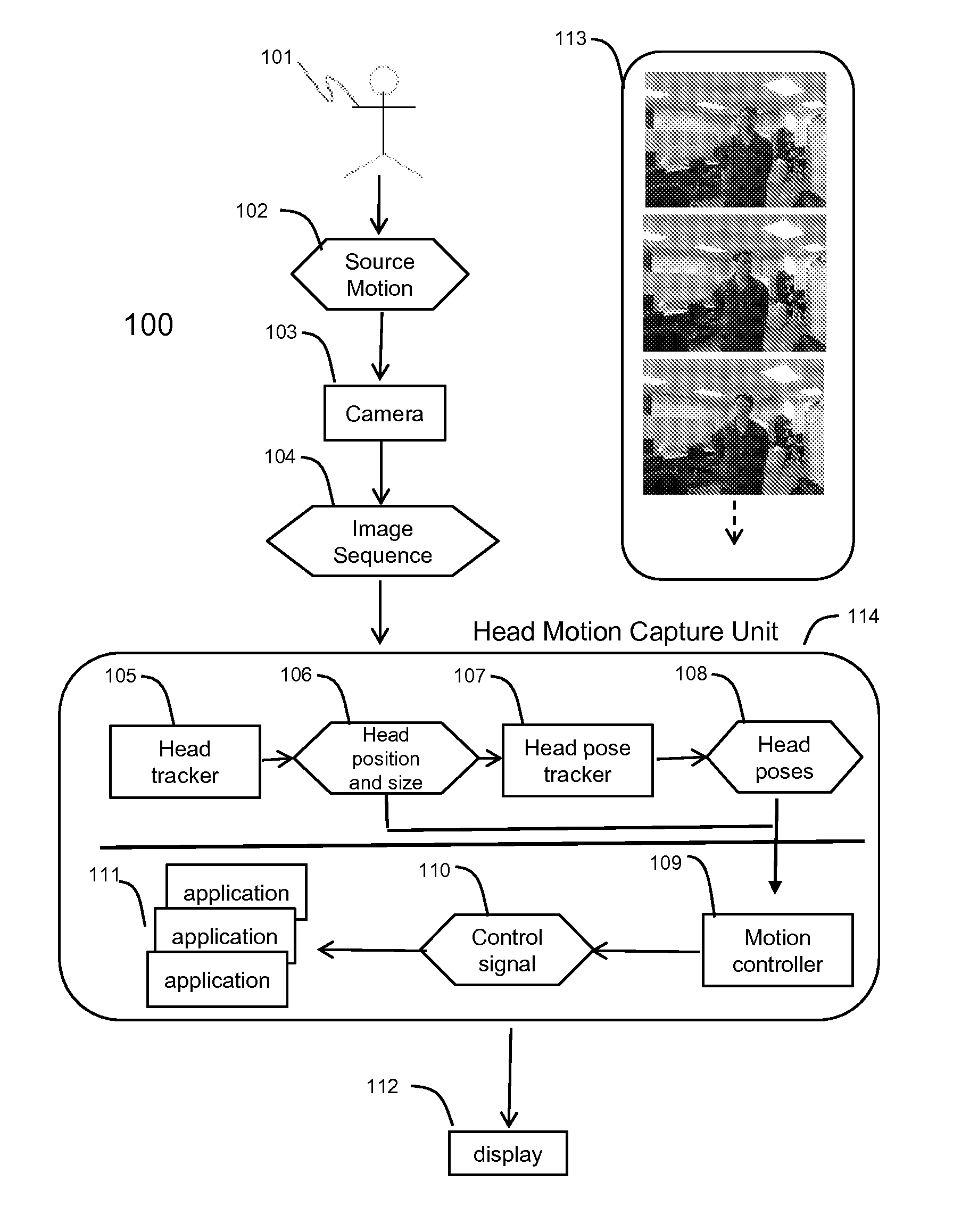
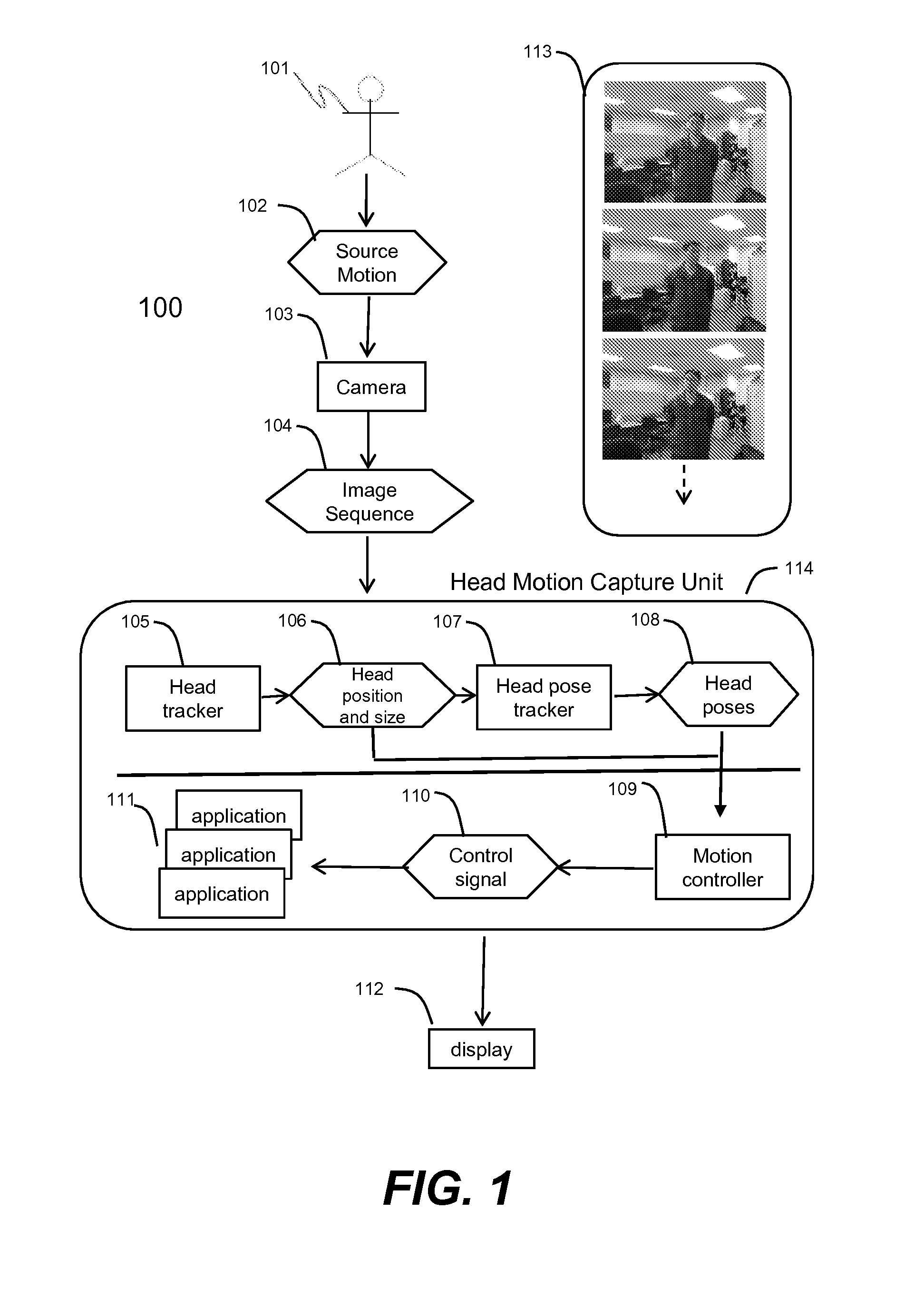
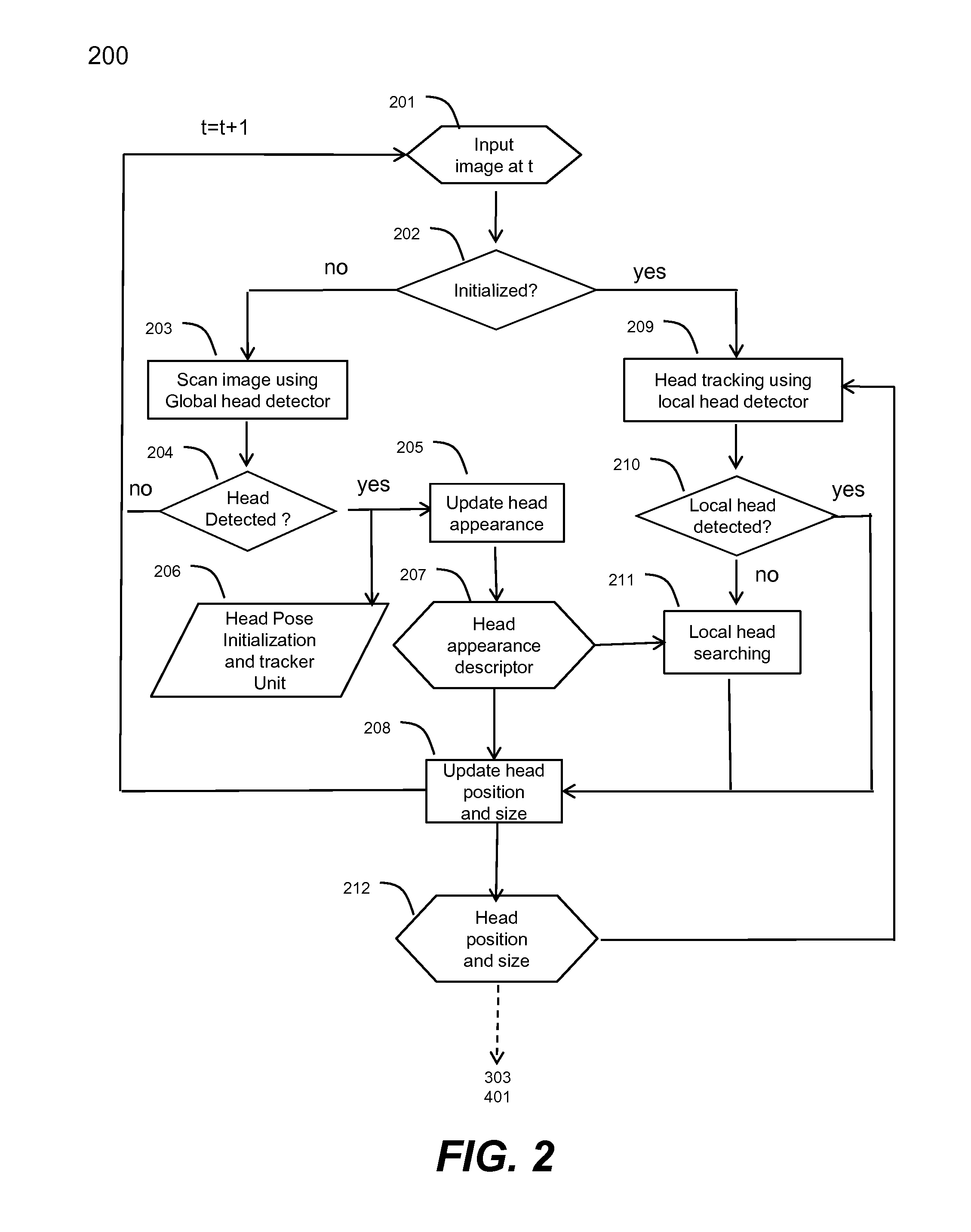
[0013]According to still another aspect of the present invention, the model-based head pose estimation performs incremental head pose estimation based on either the optical flow constraints from a set of sparse image corners localized inside the tracked head region, or the matched reference frame indexed by SURF features. Both of the head pose estimation results are integrated together using the Kalman filter with covariance derived from the sum of squared residual errors. More importantly, unlike the existing head pose estimation methods, the head pose estimation disclosed herein works well under fast and large translation motions as the facial feature tracking is integrated with a scale-invariant head tracker running robustly in real-time.

Problems solved by technology

Although people can interpret the head orientation and movement easily, head pose estimation is still remained as one of the challenging problems in computer vision due to the fact that the final pixel-based facial image is largely affected by various factors including camera geometric distortion, perspective camera projection, and varying illumination.
In these incremental estimation approaches, error accumulation degrades the estimation accuracy to the point that the final pose estimation becomes unusable.
However, pose estimation results by Morency et al and Jang et al are sensitive to large translation motion due to the local optimization of the normal flow based computation and feature point registration.
Consequently, both are not appropriate for interactive game applications, where the head of a user could have fast or large translation movements.

Method used


Image

  • Method and system for head tracking and pose estimation
  • Method and system for head tracking and pose estimation
  • Method and system for head tracking and pose estimation

Examples


Embodiment Construction

[0029]The detailed description of the invention is presented largely in terms of procedures, steps, logic blocks, processing, and other symbolic representations that directly or indirectly resemble the operations of data processing devices. These process descriptions and representations are typically used by those skilled in the art to most effectively convey the substance of their work to others skilled in the art.

[0030]Numerous specific details are set forth in order to provide a thorough understanding of the present invention. However, it will become obvious to those skilled in the art that the invention may be practiced without these specific details. In other instances, well known methods, procedures, components, and circuitry have not been described in detail to avoid unnecessarily obscuring aspects of the present invention.

[0031]Reference herein to “one embodiment” or “an embodiment” means that a particular feature, structure, or characteristic described in connection with th...


PUM


Abstract

Techniques for performing accurate and automatic head pose estimation are disclosed. According to one aspect of the techniques, head pose estimation is integrated with a scale-invariant head tracking method along with facial features detected from a located head in images. Thus the head pose estimation works efficiently even when there are large translational movements resulting from the head motion. Various computation techniques are used to optimize the process of estimation so that the head pose estimation can be applied to control one or more objects in a virtual environment and virtual character gaze control.

Description

BACKGROUND OF THE INVENTION[0001]1. Field of the Invention[0002]The invention is generally related to the area of artificial intelligence, and more particularly, related to computer vision, especially in the context of markerless head pose estimation and tracking from monocular video sequences captured by an imaging device (e.g., a video camera).[0003]2. Related Art[0004]In computer vision, head pose estimation is a process of inferring the orientation and position of a human head from digital imagery [1]. More exactly, for monocular passive optical camera based applications, it is about the estimation of the head motion in six degrees of freedom relative to a still camera, where the six degrees of freedom include three degrees of freedom for rotating along the three axes and three degrees of freedom for translating along the three axes.[0005]Although people can interpret the head orientation and movement easily, head pose estimation is still remained as one of the challenging probl...

Claims


Application Information

Patent Timeline
IPC IPC(8): H04N5/225G06K9/00
CPCG06K9/00261G06T7/0046G06K9/00335G06T2207/10016G06T2207/30201G06K2009/3291G06T7/75G06V40/167G06V10/62G06V40/20
Inventor ZHU, YOUDINGMUSICK, JR., CHARLESKAY, ROBERTPOWERS, III, WILLIAM ROBERTWILKINSON, DANAREYNOLDS, STUART
Owner YEN WEI
Why Eureka
Eureka Blog
Learn More