
Neural network fault detection system and associated methods

a neural network and fault detection technology, applied in the field of solar hot water systems, can solve problems such as damage to other system components, failures that occur far sooner, and inefficient shw systems

Inactive Publication Date: 2012-06-28
STC UNM
View PDF3 Cites 121 Cited by
  • Summary
  • Abstract
  • Description
  • Claims
  • Application Information

AI Technical Summary

Benefits of technology

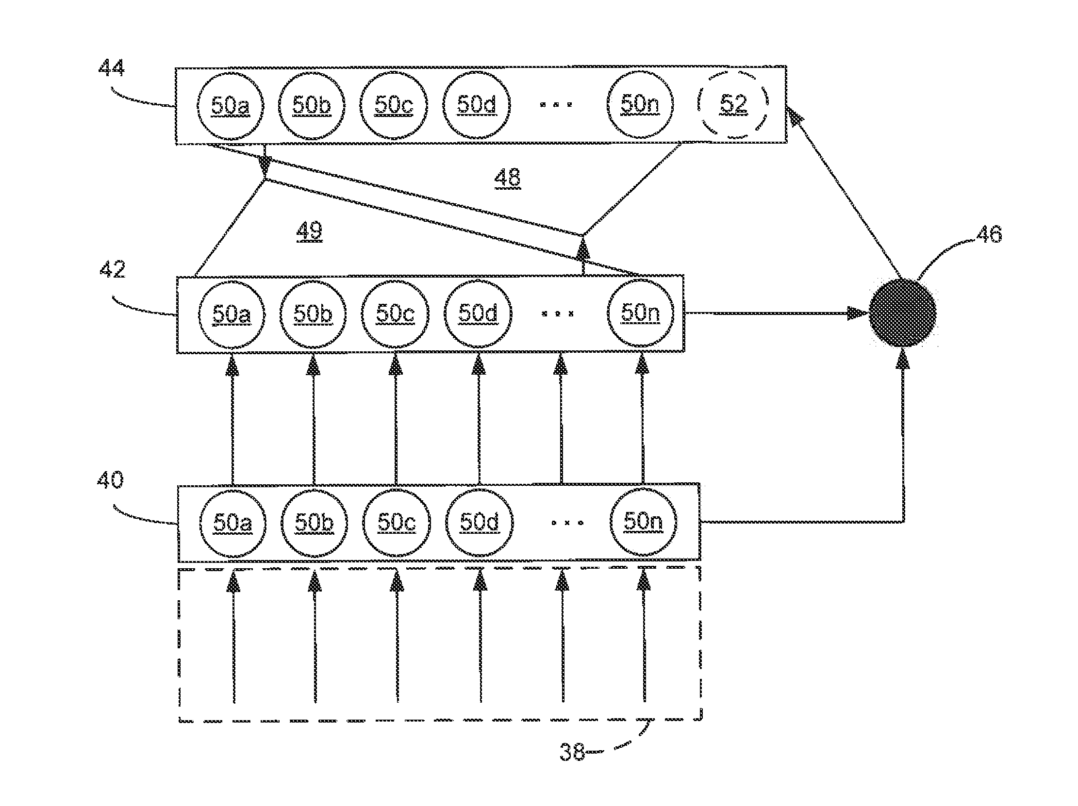
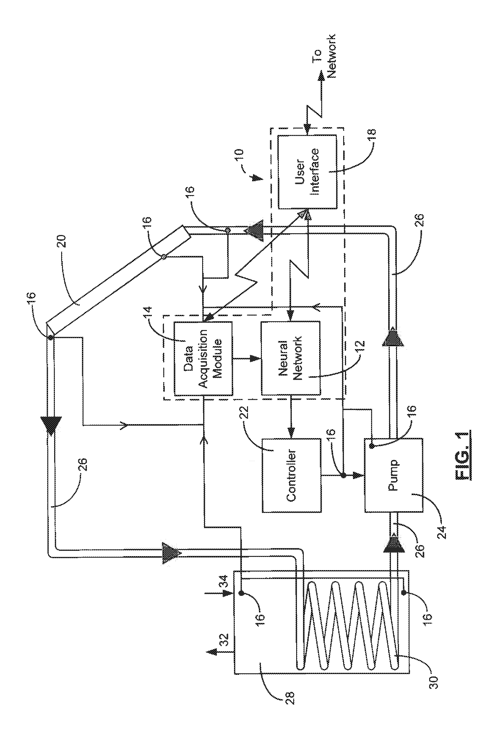
[0007]When properly trained, neural network based technology of the present invention has the capability to identify components in SHW systems that might fail based on performance anomalies, which are typically present in the system some time prior to failure. The adaptive resonance theory (ART) technology implemented in the present invention consists of detection algorithms that can be easily integrated into existing SHW system controllers, most of which are microprocessor based. With the addition of these algorithms operating in the controller, SHW system controllers may be more capable to announce a failure of a component or to predict an impending occurrence of a component failure. Furthermore, since ART technology is software based, it may be updated over time. It may be possible to regularly upload improved algorithms to existing controllers if they are connected to the internet, as many are now.
[0016]A method aspect of the present invention is for using a fault detection system with a solar hot water system. The method may include collecting the input data relating to the solar hot water system, transmitting the input data from the data acquisition module to the neural network, and executing a command to perform an analysis on the input data within the neural network. The method may also include determining the existence of a fault or a condition indicative of a potential fault, and prioritizing the fault and / or the condition indicative of the potential fault according to the analysis performed by the neural network. The method may still further include generating a warning output relating to the fault or the condition indicative of the potential fault responsive to the analysis, and displaying the warning output on the user interlace. The method may also provide a prompt that allows a user to make a choice using the user interface. The choice may include any one or more of shutting down the solar hot water system, viewing more information relating to the warning output, waiting a time period and reviewing a new warning output at a later time, or ignoring the warning output. The method may also include transmitting an output control signal relating to operation of the solar hot water system from the neural network to the controller.

Problems solved by technology

However, in many cases, failures occur far sooner due to a variety of problems, many of which are undetected or detected long after the system has failed.
Some failures may cause the SHW system to run inefficiently, or, in some cases, damage other system components.
Of most concern is the fact that these failures cause the system to stop converting renewable energy, creating a draw of energy from the grid or other producers.
This is disadvantageous to the environment, the owner of the SHW system, and any entity, such as a government, that may provide incentives related to SHW systems.
In many failure scenarios, the fault goes unnoticed by the SHW system owner because the backup energy source, typically a gas-fired or electric backup system, produces energy to heat the water.
Unless the owner diligently monitors the SHW system's operation, the fault may go unnoticed for weeks, or, in some cases, years.
If such data exist, failures of components can be predicted with some fixed probability, and the user can then choose to replace components preemptively, before a failed component creates a system failure.
Unfortunately, these statistics are unknown for SHW systems.
As a result, SHW systems fail at a relatively high rate.
Collection of end-of-life data, however, is a very expensive and long-term endeavor.
Unfortunately, some of the sensors of the Farrington et al.
'832 system are expensive, such as the flow rate sensor.
The low cost of SHW systems does not warrant the installation of such apparatus, especially for residential units.

Method used


Image

  • Neural network fault detection system and associated methods
  • Neural network fault detection system and associated methods
  • Neural network fault detection system and associated methods

Examples


Embodiment Construction

[0030]The present invention will now be described more fully hereinafter with reference to the accompanying drawings, in which preferred embodiments of the invention are shown. This invention may, however, be embodied in many different forms and should not be construed as limited to the embodiments set forth herein. Rather, these embodiments are provided so that this disclosure will be thorough and complete, and will fully convey the scope of the invention to those skilled in the art. Like numbers refer to like elements throughout.

[0031]In this detailed description of the present invention, a person skilled in the art should note that directional terms, such as “above,”“below,”“upper,”“lower,” and other like terms are used for the convenience of the reader in reference to the drawings. Also, a person skilled in the art should notice this description may contain other terminology to convey position, orientation, and direction without departing from the principles of the present inven...


PUM


Abstract

A fault detection system for use with a solar hot water system may include a data acquisition module which may, in turn, include a plurality of sensors. Input data may include a sensed condition. The system may also include a neural network to receive the input data which may be a multi-layer hierarchical adaptive resonance theory (ART) neural network. The neural network may perform an analysis on the input data to determine existence of a fault or a condition indicative of a potential fault. The fault and the condition indicative of the potential fault are prioritized according to the analysis performed by the neural network. A warning output relating to the fault and the condition indicative of the potential fault is generated responsive to the analysis, and is displayed on the user interface.

Description

RELATED APPLICATIONS[0001]This application claims priority from U.S. Provisional Patent Application Ser. No. 61 / 460,039 filed on Dec. 23, 2010 by the inventors of the present application and titled REAL-TIME FAULT DETECTION SYSTEM AND METHODS, the entire contents of which are incorporated herein by reference.FIELD OF THE INVENTION[0002]The present invention relates to the field of solar hot water systems and, more specifically, to fault prediction systems for solar hot water systems.BACKGROUND OF THE INVENTION[0003]Solar hot water (SHW) systems are generally expected to last for 20 years with little or no maintenance. However, in many cases, failures occur far sooner due to a variety of problems, many of which are undetected or detected long after the system has failed. Some failures may cause the SHW system to run inefficiently, or, in some cases, damage other system components. Of most concern is the fact that these failures cause the system to stop converting renewable energy, cr...

Claims


Application Information

Patent Timeline
Patent Type & Authority Applications(United States)
IPC IPC(8): G06N7/04G06F17/00G06N3/02
CPCG06N3/0409G05B23/024
Inventor HE, HONGBOMAMMOLI, ANDREACAUDELL, THOMAS
Owner STC UNM
Learn More