
System and method to eliminate a hard rub and optimize a purge flow in a gas turbine

Inactive Publication Date: 2012-06-28
GENERAL ELECTRIC CO
View PDF3 Cites 25 Cited by
  • Summary
  • Abstract
  • Description
  • Claims
  • Application Information

AI Technical Summary

Benefits of technology

[0006]In another embodiment a method of providing a gas turbine is provided. The method includes providing a stator configured to guide a flow of an incoming gas. The method also includes providing a rotor configured to expand the incoming gas and extract kinetic energy from the incoming gas. The method further includes providing a purge flow bled from a compressor and configured to reduce a temperature of a wheel space by limiting ingestion of the incoming gas. The method also includes providing an angel wing disposed between the rotor and the stator and configured to act as a sealing surface between the rotor and the stator. The method further includes providing a fan blade disposed on a surface of the angel wing at an axial position and configured to generate a recirculation zone of the purge flow, wherein the recirculation zone reduces a volume of a successive purge flow entering the wheel space.

Problems solved by technology

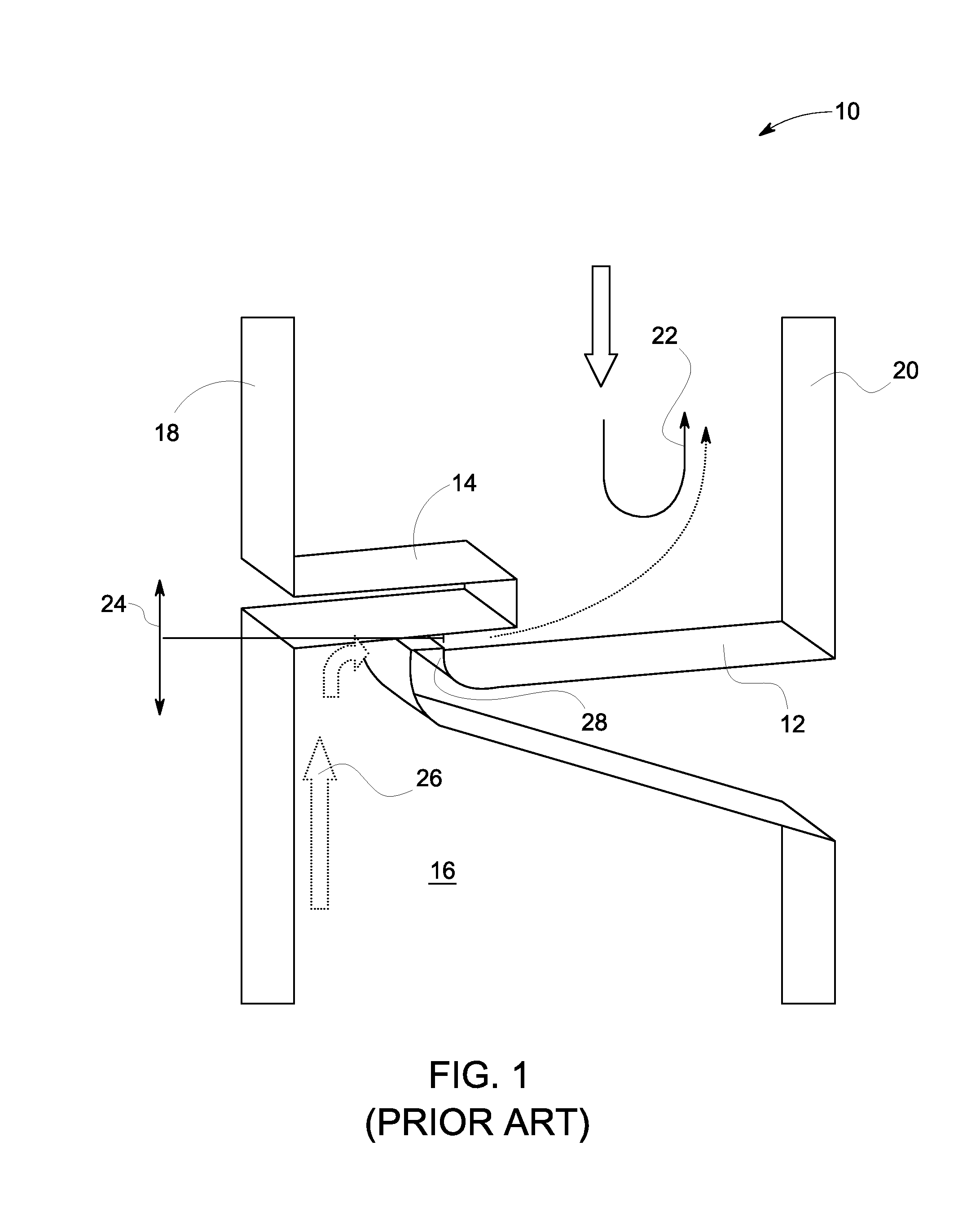
During operation of the turbine, an undesired ingestion of the incoming gas into the wheel space can result in overheating of the metal components.
However, maintaining the adequate purge flow in the wheel space, during the operation of the gas turbine, results in complexities, costs and maintenance.
The tip reduces the clearance area between the angel wing and the discourager resulting in a reduction of the purge flow to a desirable limit for maintaining an acceptable temperature within the wheel space.
However, the tip of the angel wing generally generates an undesirable hard rub between the discourager and the tip during a startup of the turbine.
The hard rub results in deterioration of the discourager and wear of the angel wing, leading to an increase in the clearance area that further results in an undesirable increase in the purge flow and maintenance costs.

Method used


Image

  • System and method to eliminate a hard rub and optimize a purge flow in a gas turbine
  • System and method to eliminate a hard rub and optimize a purge flow in a gas turbine
  • System and method to eliminate a hard rub and optimize a purge flow in a gas turbine

Examples


Embodiment Construction

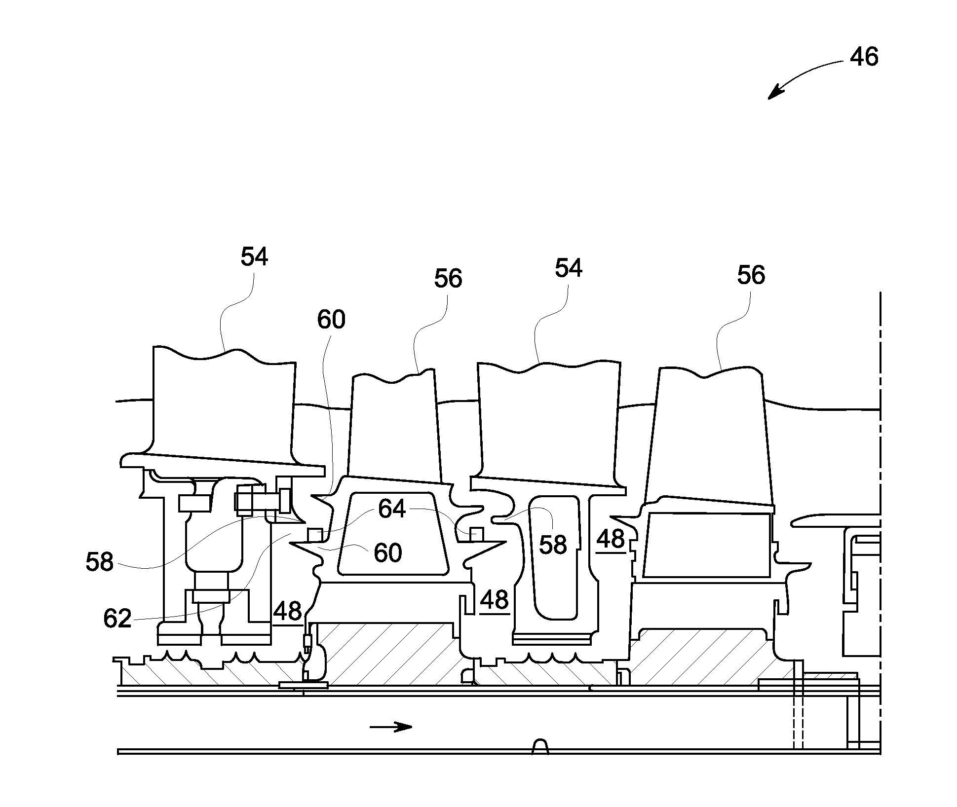
[0017]As discussed in detail below, embodiments of the present invention include a system and method to eliminate a hard rub and optimize a purge flow in a gas turbine. In one embodiment, the system includes an angel wing without a tip that eliminates the hard rub between the angel wing and a discourager. As referred to herein, the term ‘hard rub’ is defined as a rub during startup of the turbine between metal components of the angel wing tip and the discourager. Furthermore, a fan blade is disposed on the angel wing that generates a recirculation zone of the purge flow to reduce a volume of successive purge flows entering a wheel space. As used herein, the term ‘purge flow’ is defined as a gas flow entering the wheel space from a clearance area to prevent overheating and to maintain an acceptable temperature in the wheel space. As referred to herein, the ‘clearance area’ is defined as a gap between the discourager and the angel wing. In another embodiment, the angel wing tip is ret...


PUM


Abstract

A system and method to eliminate hard rub and optimize a purge flow in a gas turbine is provided. The gas turbine includes a stator configured to guide a flow of an incoming gas. The gas turbine also includes a rotor configured to expand the incoming gas and extract kinetic energy from the incoming gas. The gas turbine further includes a purge flow bled from a compressor and configured to reduce a temperature of a wheel space by limiting ingestion of the incoming gas. The gas turbine also includes an angel wing disposed between the rotor and the stator and configured to act as a sealing surface between the rotor and the stator. The gas turbine further includes a fan blade disposed on a surface of the angel wing at an axial position and configured to generate a recirculation zone of the purge flow, wherein the recirculation zone is reduces a volume of successive purge flows entering the wheel space.

Description

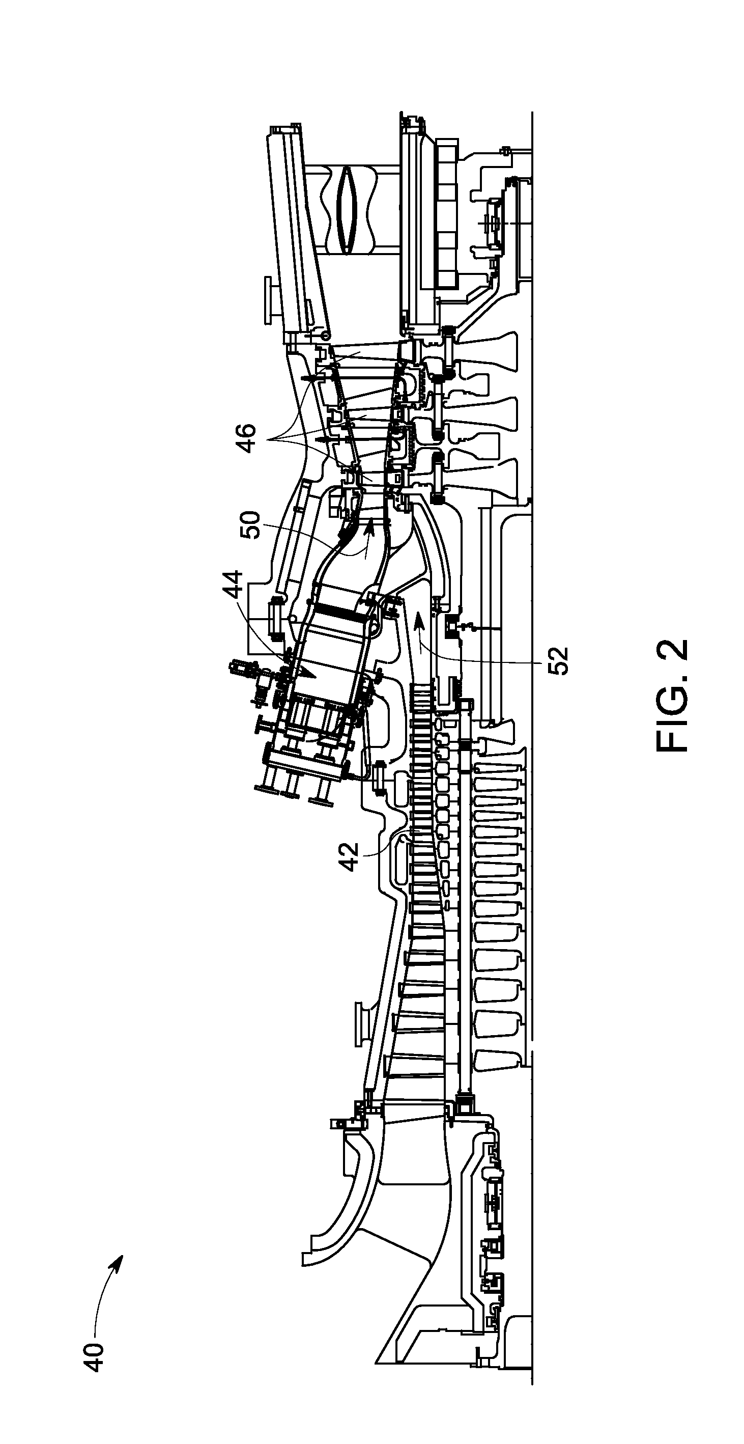
BACKGROUND[0001]The invention relates generally to a gas turbine and more particularly, to a system and a method to reduce wheel space purge flow without risking a hard rub in a gas turbine.[0002]Generally, a gas turbine typically comprises a compressor, a combustor and a turbine. The turbine further includes multiple wheel spaces wherein each of the multiple wheel spaces includes a rotor and a stator. The stator includes vanes or nozzles that guide the flow of an incoming gas to the rotor. The rotor, in an example, includes blades or buckets that extract work from the incoming gas received from the stator. During operation of the turbine, an undesired ingestion of the incoming gas into the wheel space can result in overheating of the metal components. In some embodiments, a purge flow is directed into the wheel space via a clearance area to prevent the incoming gas ingestion and associated overheating. Typically, an adequate purge flow needs to be maintained to sustain an acceptabl...

Claims


Application Information

Patent Timeline
IPC IPC(8): F01D11/08
CPCF01D11/02F01D11/06F05D2240/127F05D2240/126F05D2240/125
Inventor DEVI, RAVINDRA GOPALDASWOLFE, CHRISTOPHER EDWARDSHENG, NUO
Owner GENERAL ELECTRIC CO
Learn More