
Touch screen

a touch screen and touch technology, applied in the field of touch screens, can solve the problems of no longer simple devices, inconvenient operation of touch screens, and terminals such as mobile phones, and achieve the effect of reducing process time and increasing production yield

Inactive Publication Date: 2012-06-28
SAMSUNG ELECTRO MECHANICS CO LTD
View PDF6 Cites 128 Cited by
  • Summary
  • Abstract
  • Description
  • Claims
  • Application Information

AI Technical Summary

Benefits of technology

[0010]The present invention has been made in an effort to provide a touch screen fabricated by designing the touch screen to enable drive signals to be input on both sides of the touch screen, to thereby overcome obscured screen problems due to an input device, and by simultaneously forming transparent electrodes and electrode wires to thereby increase production yield while reducing a process time.

Problems solved by technology

However, with advanced mobile communication technologies, terminals such as a mobile phone, a PDA, a navigation, or the like, are no longer simple devices for displaying textual information only, but have developed as complex and various kinds of devices with increased performance to include multimedia such as audio, video, wireless internet web browser, or the like.
In this case, the input means may obscure a screen of an image display unit which causes inconvenience in operating the touch screen and increases the occurrence of mis-operation.
Consequently, the number of electrode wires in the touch screen is increased, which in turn causes an increase in area of a bezel region of the touch screen, and as a result, it is difficult to decrease the size of an electronic product.

Method used


Image

  • Touch screen
  • Touch screen
  • Touch screen

Examples


first preferred embodiment

of Invention

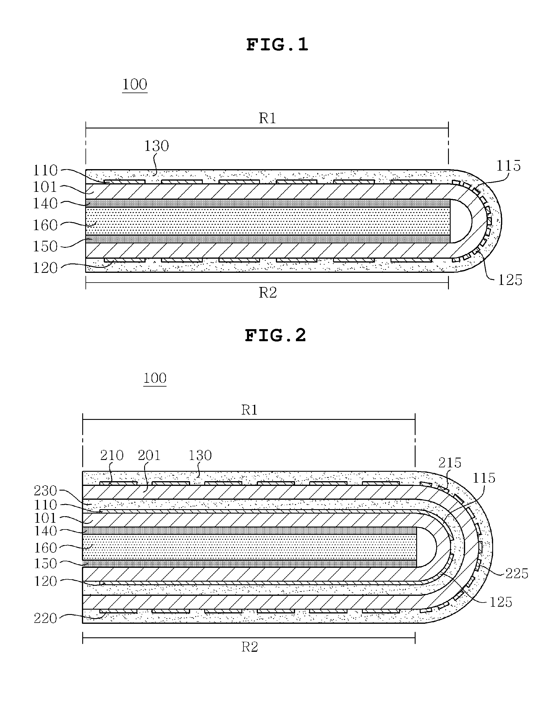
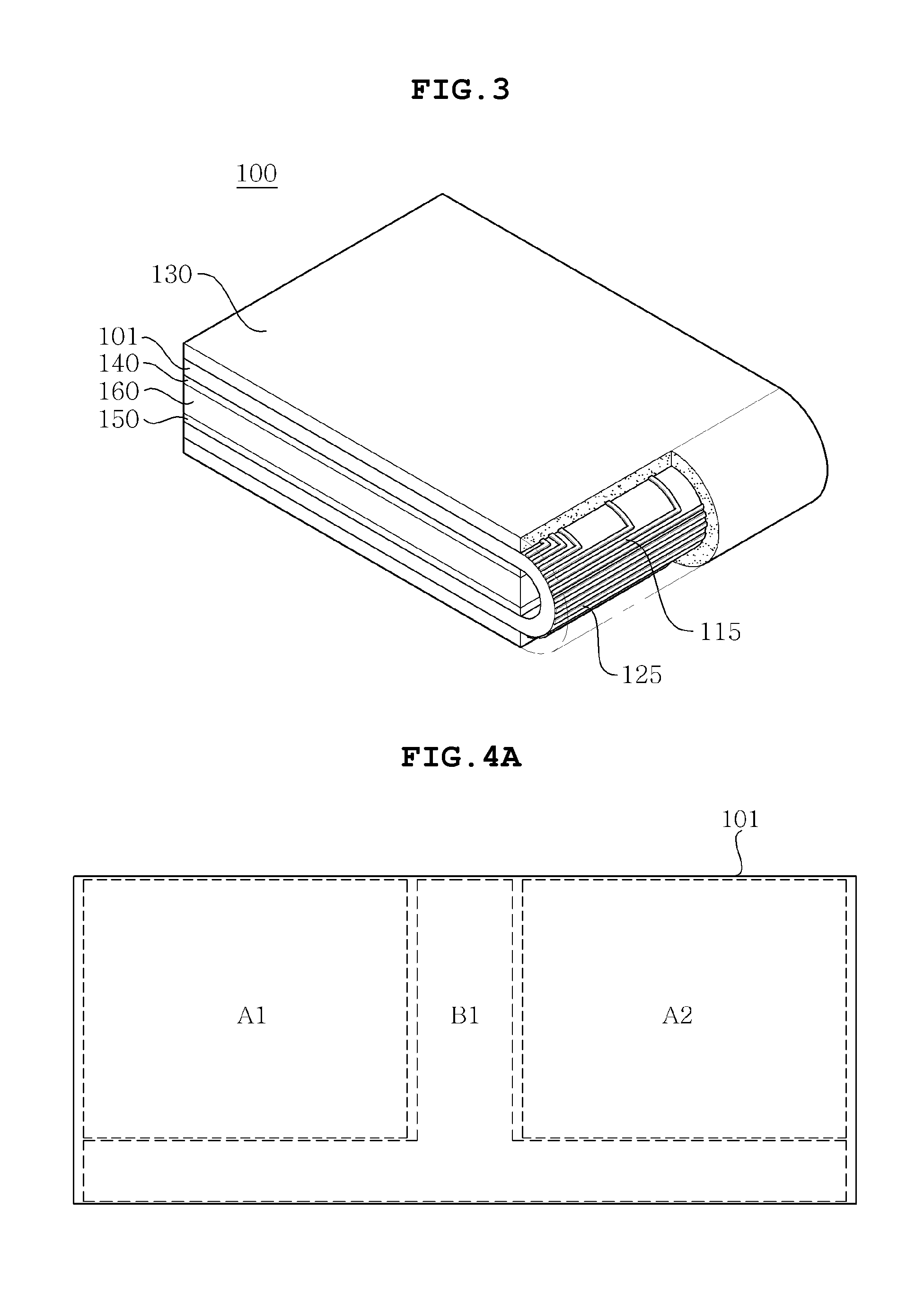
[0039]FIG. 1 is a cross-sectional view showing a touch screen according to a first preferred embodiment of the present invention, and FIG. 3 is a perspective view showing the touch screen according to the first preferred embodiment of the present invention.

[0040]As shown in FIG. 1, a touch screen 100 according to the first embodiment of the present invention includes a first transparent substrate 101, first transparent electrodes 110 and second transparent electrodes 120, first electrode wires 115 and second electrode wires 125, and a first image display unit 140 and a second image display unit 150, and the like.

[0041]The first transparent substrate 101 may function to afford a region on which transparent electrodes (the first transparent electrodes 110 and the second transparent electrodes 120) and electrode wires (the first electrode wires 115 and the second electrode wires 125) are provided. As shown in FIG. 4A, the first transparent substrate 101 is partitioned into ...

second preferred embodiment

of Invention

[0055]FIG. 2 is a cross-sectional view illustrating a touch screen according to a second preferred embodiment of the present invention.

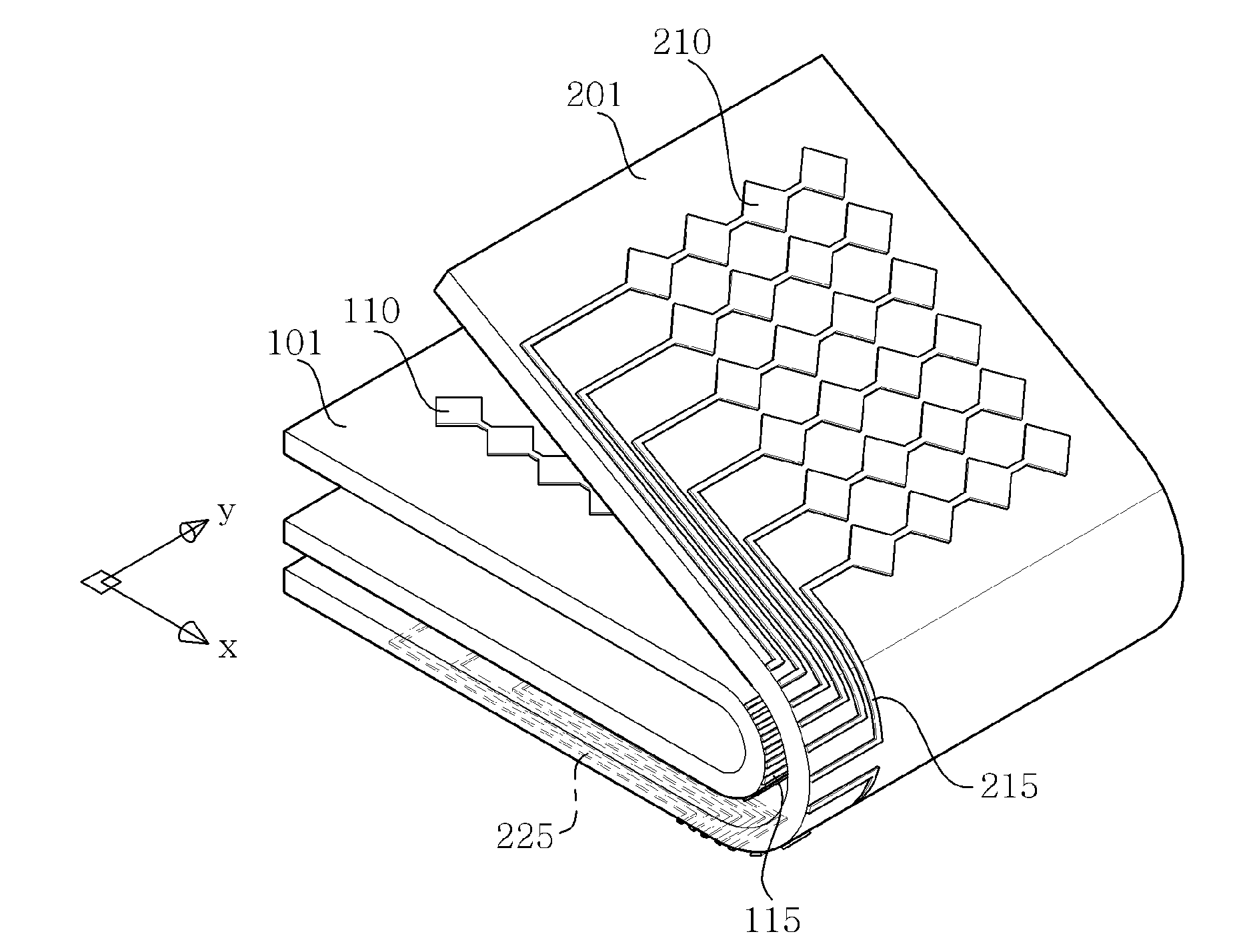
[0056]As shown in FIG. 2, a touch screen 100 according to the second preferred embodiment of the present invention may be fabricated in a double-structure, including: a first transparent substrate 101 on which transparent electrodes 110 and 120, as well as electrode wires 115 and 125, are formed; a second transparent substrate 201 on which transparent electrodes (third transparent electrodes 210 and fourth transparent electrodes 220), as well as electrode wires (third electrode wires 215 an fourth electrode wires 225), are formed; two image display units 140 and 150; and an adhesive layer 230. That is, one side of the second transparent substrate 201 is arranged to face the other side of the first transparent substrate 101 and both of them are bonded by the adhesive layer 230. Here, the first transparent substrate 101 is folded to allow t...


PUM


Abstract

Disclosed herein is a touch screen 100 designed to control an image displayed on image display units 140 and 150 on both-sides of the touch screen. The touch screen 100 according to the present invention may overcome an obscured screen problem caused by an input device, increase production yield while reducing a process time of the touch screen 100 by simultaneously forming transparent electrodes and electrode wires on a transparent substrate and, after forming an image display unit and an active region on the transparent substrate, folding the transparent substrate, and minimize an area of a bezel region.

Description

CROSS REFERENCE TO RELATED APPLICATION[0001]This application claims the benefit of Korean Patent Application No. 10-2010-0134688, filed on Dec. 24, 2010, entitled “Touch Screen” which is hereby incorporated by reference in its entirety into this application.BACKGROUND OF THE INVENTION[0002]1. Technical Field[0003]The present invention relates to a touch screen.[0004]2. Description of the Related Art[0005]With advanced computers using digital technologies, computer-assisted equipment has also been developed. Further, personal computers, portable transmission devices, other personal private information processing devices, or the like, normally execute text and graphic functions by using various input devices such as a keyboard, a mouse, or the like.[0006]However, with advanced mobile communication technologies, terminals such as a mobile phone, a PDA, a navigation, or the like, are no longer simple devices for displaying textual information only, but have developed as complex and vari...

Claims


Application Information

Patent Timeline
Patent Type & Authority Applications(United States)
IPC IPC(8): G06F3/041
CPCG06F3/0412G06F3/044G06F3/0416G06F3/04164G06F3/0443G06F3/0445G06F3/0446G06F2203/04103G06F3/0448
Inventor YOO, DONG SIKLEE, HEE BUMCHAE, KYOUNG SOOOH, YONG SOOHONG, YUN KILEE, JONG YOUNG
Owner SAMSUNG ELECTRO MECHANICS CO LTD
Learn More