
Motorized beach cart

a beach cart and motor technology, applied in the field of beach carts, can solve the problems of dragging and/or pulling such a cart, affecting the use of beach carts,

Active Publication Date: 2012-06-28
ANASIEWICZ STEPHEN A
View PDF22 Cites 29 Cited by
  • Summary
  • Abstract
  • Description
  • Claims
  • Application Information

AI Technical Summary

Benefits of technology

[0014]Accordingly, it is an aspect of the present invention to provide a motorized cart that is collapsible for easy storage and is stable in multiple configurations for differing transportation situations.
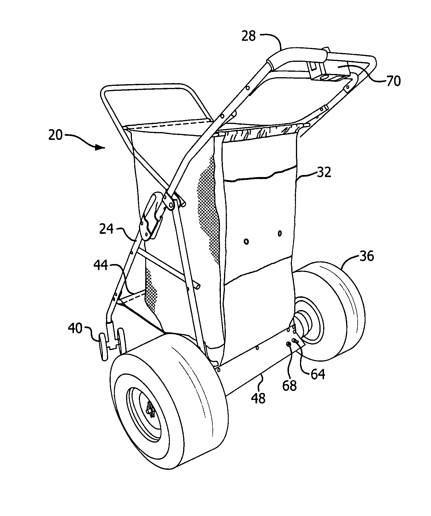
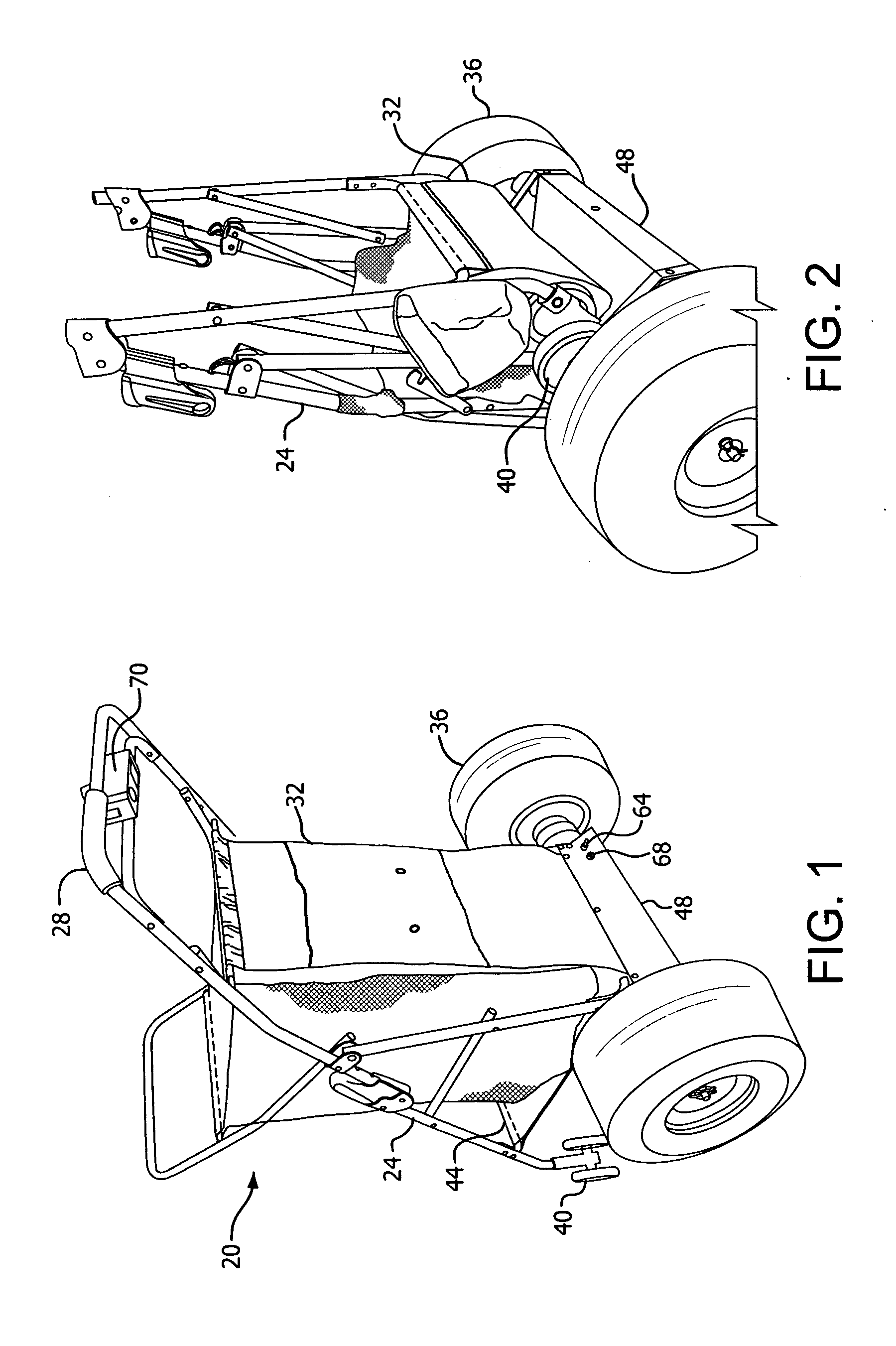
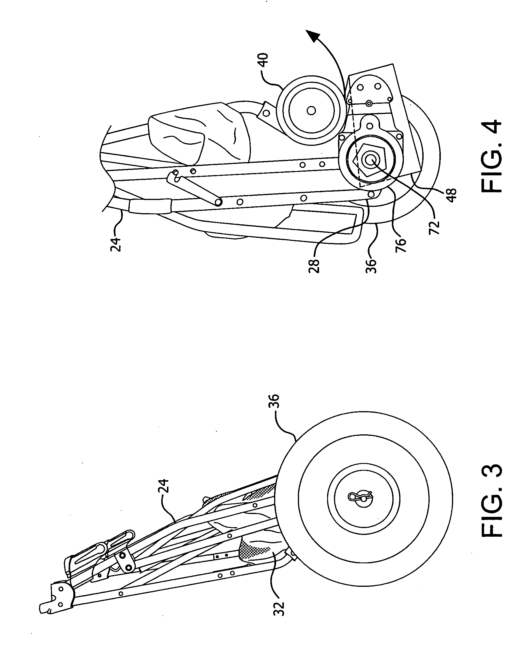
[0015]The foregoing and / or other aspects of the present invention are achieved by providing a motorized cart, including: a collapsible frame having a handle and a collapsible storage compartment connected to the frame; and at least three wheels, including a front wheel and two rear wheels disposed at a rear of the frame for rotating about a single axis. The cart also includes means for connecting the rear wheels at a rear of the frame for rotating about a single axis, and a folding support platform including first and second portions hingedly connected to each other. The first portion rotatably connects at a front of the frame, and the second portion rotatably connects at the rear of the frame. The cart additionally includes a drive compartment housing a battery, a drive controller, and at least one motor electrically connected to the battery and the drive controller for driving at least one of the rear wheels. The drive compartment is positioned on the frame to position the battery, the drive controller, and the motor below and forward of the rear wheel rotation axis when the cart is in an expanded, upright mode, thereby positioning a center of gravity of the cart forward of the rear wheel rotation axis to enhance stability. The drive compartment is shaped and positioned on the frame to permit the collapsing of the storage compartment and the frame to a collapsed mode for compact storage of the cart, and to provide clearance for the at least one front wheel during transition between the collapsed mode and the expanded, upright mode. The drive compartment is positioned on the frame to substantially vertically align the center of gravity of the cart with the rear wheel rotation axis in a tilted mode, in which the cart operates on the two rear wheels.

Problems solved by technology

Pushing and / or pulling such a cart, particularly if heavily laden, can be inconvenient.
But these carts lack features that are focused on the needs of beach cart users.
In a beach environment, such exposed equipment would degrade quickly and could easily become clogged with sand.
Additionally, although the cart is disclosed as having an attachable basket, in such a configuration the cart cannot be collapsed for storage.
U.S. Pat. No. 4,106,583 to Nemeth discloses a self-powered folding golf cart that has a battery housing that is disposed fairly high on the device and may pose stability issues.
Additionally, although the front wheel and the rear legs are collapsible, the device lacks a collapsible storage compartment.
But this device also lacks a collapsible storage compartment.
Motorized beach carts are also known, but lack features desired by beach-goers.
The device lacks the ability to store compactly.
While convenient in these two configurations, this device is also not easily storable in a compact manner.
Both of these devices, however, require complex and / or expensive specialized equipment to provide the stair-climbing ability.
Such equipment may not fare well in the salt and sand of the beach.

Method used


Image

  • Motorized beach cart
  • Motorized beach cart
  • Motorized beach cart

Examples


Embodiment Construction

[0014]Accordingly, it is an aspect of the present invention to provide a motorized cart that is collapsible for easy storage and is stable in multiple configurations for differing transportation situations.

[0015]The foregoing and / or other aspects of the present invention are achieved by providing a motorized cart, including: a collapsible frame having a handle and a collapsible storage compartment connected to the frame; and at least three wheels, including a front wheel and two rear wheels disposed at a rear of the frame for rotating about a single axis. The cart also includes means for connecting the rear wheels at a rear of the frame for rotating about a single axis, and a folding support platform including first and second portions hingedly connected to each other. The first portion rotatably connects at a front of the frame, and the second portion rotatably connects at the rear of the frame. The cart additionally includes a drive compartment housing a battery, a drive controlle...


PUM

PropertyMeasurementUnit
diameteraaaaaaaaaa
diameteraaaaaaaaaa
widthaaaaaaaaaa

Abstract

A motorized cart, including: a collapsible frame with a collapsible storage compartment, a front wheel, and two rear wheels rotating about a single axis. The frame has a folding support platform including hingedly connected first and second portions. The first portion rotatably connects at a front of the frame, and the second portion rotatably connects to a rear of the frame. A drive compartment houses a battery, a drive controller, and a motor for driving a rear wheel, and is positioned on the frame to position the battery, the drive controller, and the motor below and forward of the axis in an expanded, upright mode, thereby positioning a cart center of gravity forward of the axis. The drive compartment is shaped and positioned on the frame to: permit the collapsing of the storage compartment and the frame to a collapsed mode; provide clearance for the front wheel during transition between the collapsed mode and the expanded, upright mode; and substantially vertically align the cart center of gravity with the axis in a tilted mode, operating only on the two rear wheels.

Description

CROSS-REFERENCE TO RELATED APPLICATION[0001]This application is a continuation-in-part of U.S. application Ser. No. 12 / 929,015, filed Dec. 22, 2010, the disclosure of which is incorporated herein by reference in its entirety.BACKGROUND OF THE INVENTION[0002]1. Field of the Invention[0003]The present invention relates generally to beach carts, and more particularly, to a motorized beach cart.[0004]2. Description of the Related Art[0005]Many beach-goers drive to parking lots relatively near the beach, and from there make many trips to ferry all the desired equipment, such as chairs, umbrellas, and coolers to the beach. Thus, a beach cart for carrying such items is desirable to reduce the number of trips. Such a cart, however, is typically transported in or on the car to and from the parking lot. Pushing and / or pulling such a cart, particularly if heavily laden, can be inconvenient. To ease the physical burden on the beachgoer, a motorized cart is desirable. Many examples of motorized ...

Claims


Application Information

Patent Timeline
Patent Type & Authority Applications(United States)
IPC IPC(8): B62D51/04H05K13/04
CPCB62D51/04B62B1/002B62B2202/52B62B5/0033Y10T29/49002B62B3/02B62B2203/00B62B2301/25B62B5/0069
Inventor ANASIEWICZ, STEPHEN A.
Owner ANASIEWICZ STEPHEN A
Learn More