
Apparatus and Method for the Electrolysis of Water

a technology of electrolysis device and water, which is applied in the direction of hydrocarbon oil refining, oxygen compound preparation by reduction, energy input, etc., can solve the significant disadvantages of relying on non-renewable and polluting resources, prohibitive cost of current precious metal electrodes, and non-competitive electrolysis process with conventional hydrocarbon processes. achieve the effect of reducing the amount of electrocatalytic precious metal, maintaining efficient hydrogen production, and cost-effective and efficien

Inactive Publication Date: 2012-06-14
UT BATTELLE LLC
View PDF1 Cites 51 Cited by
  • Summary
  • Abstract
  • Description
  • Claims
  • Application Information

AI Technical Summary

Benefits of technology

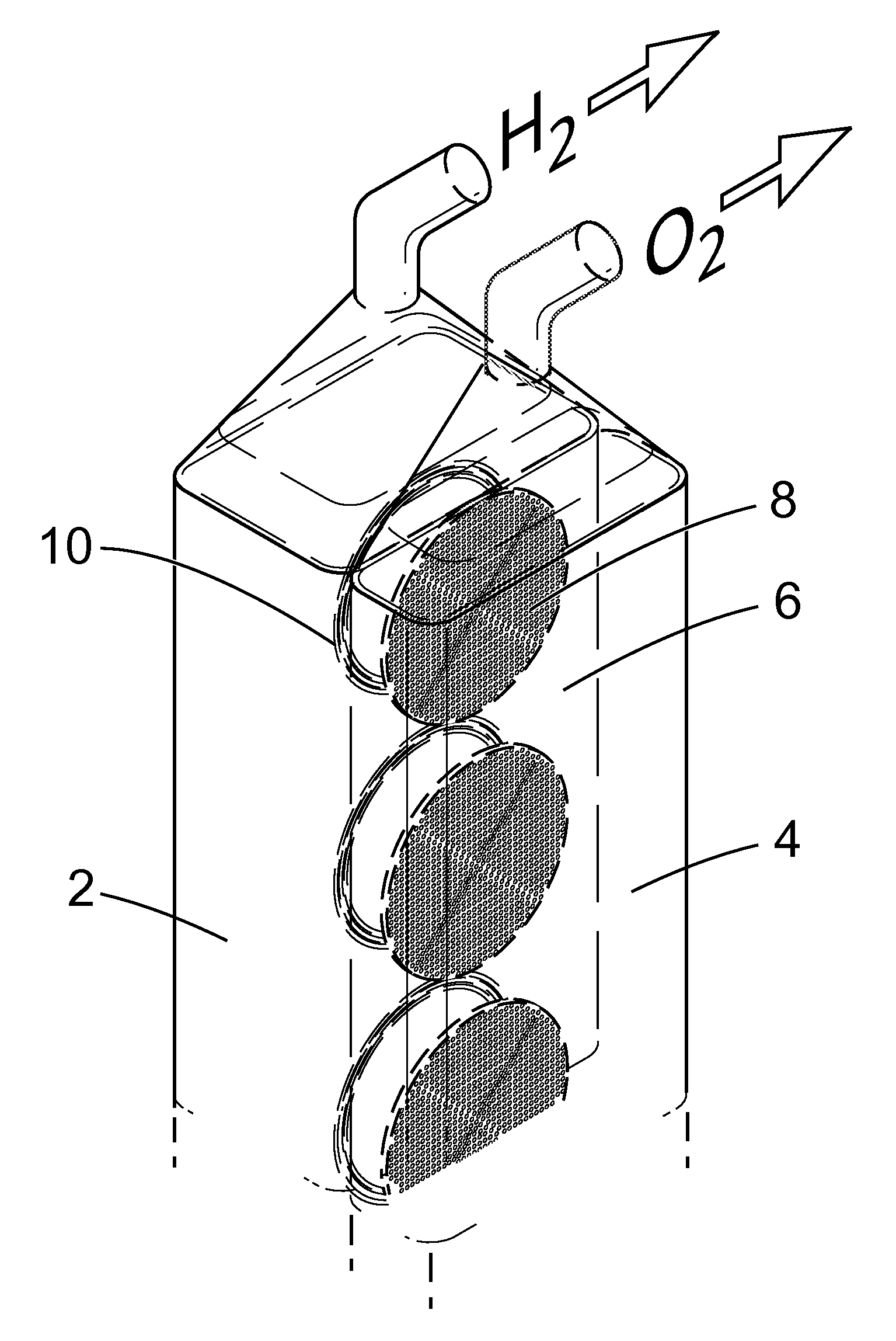
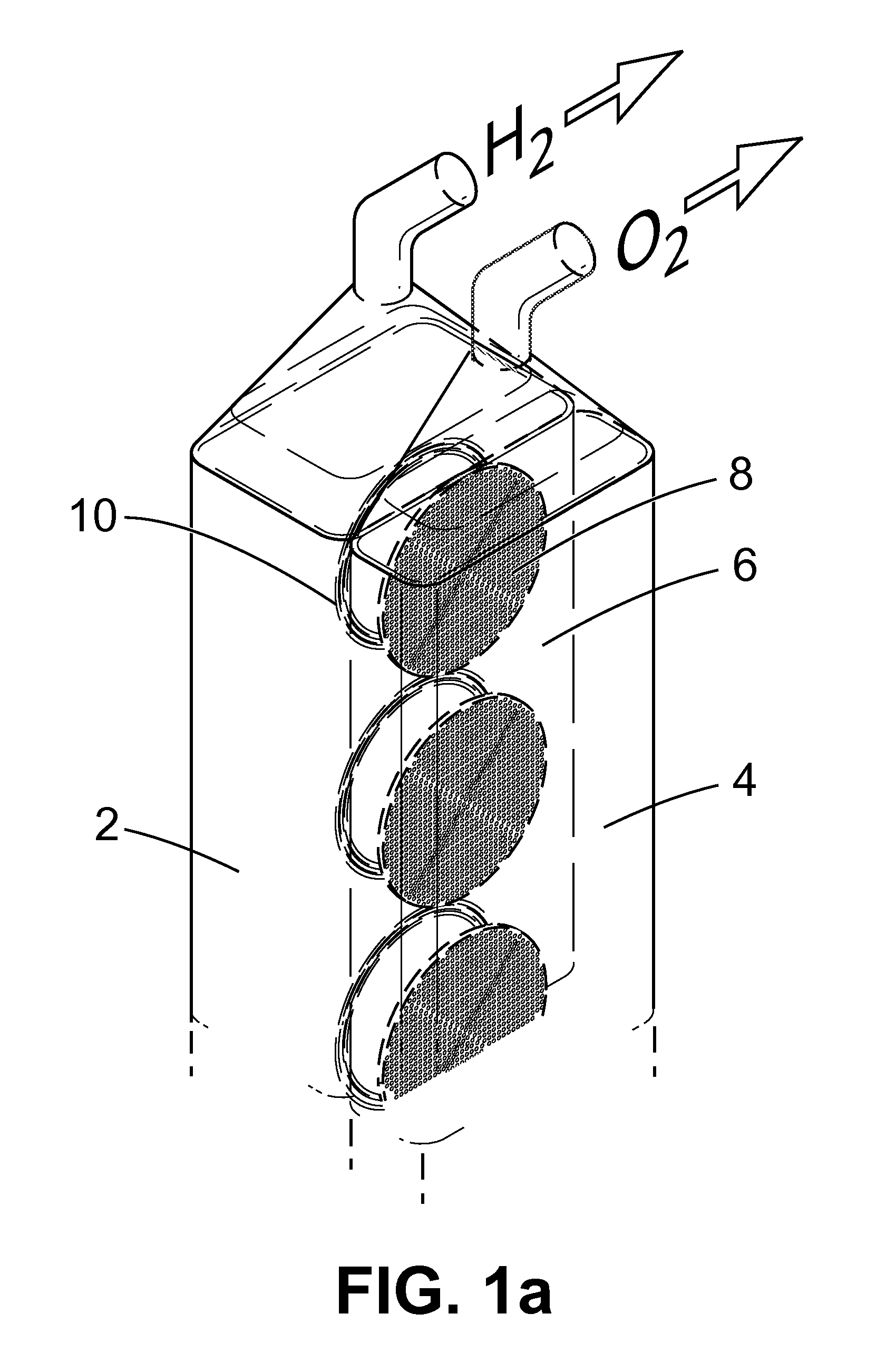
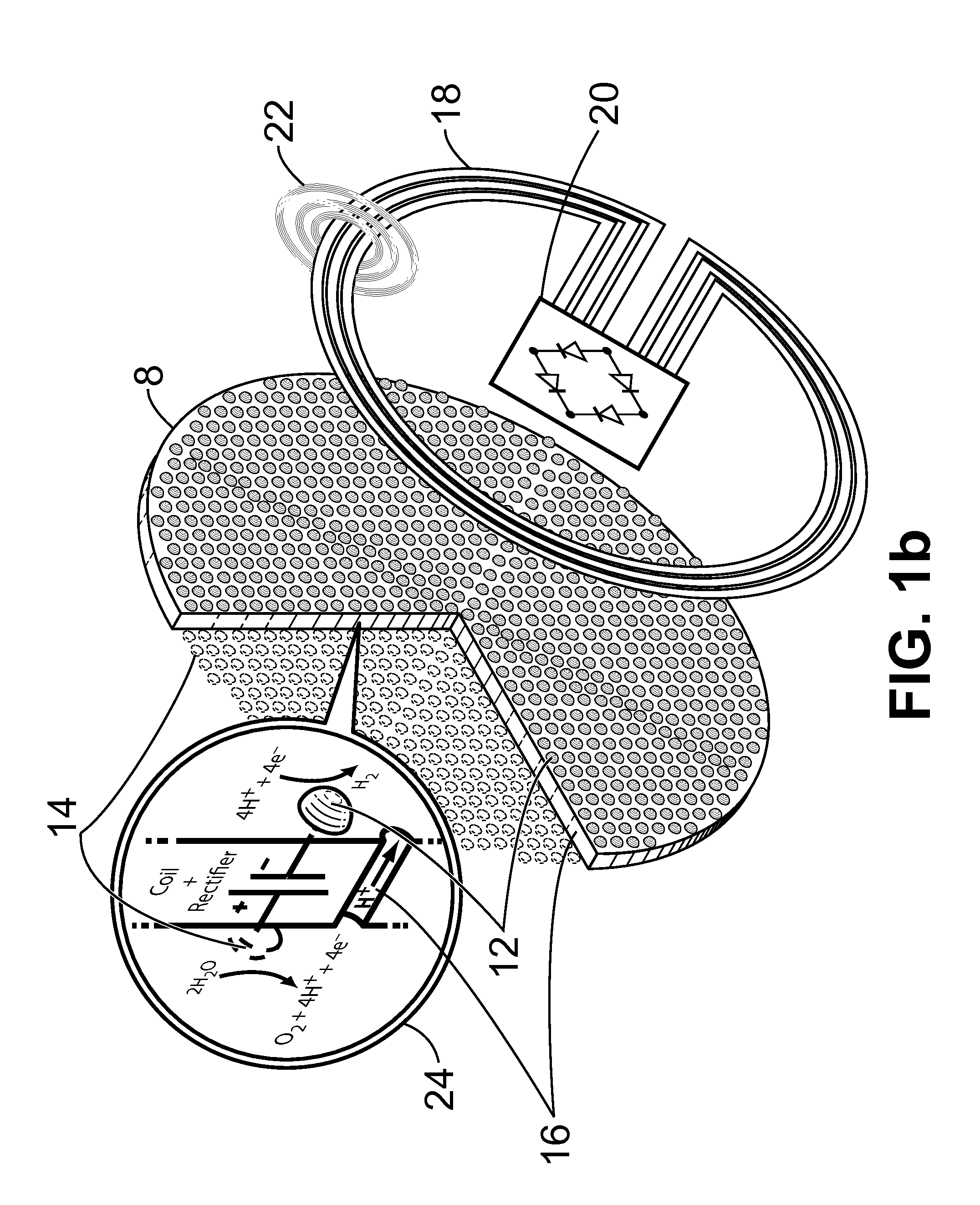
[0014]A first particular advantage provided by the instant electrolytic system is the significantly reduced amount of electrocatalytic precious metal needed, as compared to bulk precious metal electrodes, for producing an equivalent amount of hydrogen or oxygen. A second particular advantage provided by the instant electrolytic system is, in particular embodiments, the ability to dispense with a proton-conducting membrane (i.e., proton-exchange or polymer-electrolyte membrane) or any barrier that functions to separate the anode and cathode or place the anode and cathode in separate compartments. A third particular advantage provided by the instant electrolytic system is the ability of the system to maintain efficient production of hydrogen and oxygen gas even if one or a certain number of microscaled electrodes fails. A fourth particular advantage provided by the instant electrolytic system is the ability of the system to be significantly scaled up by increasing the number of microscaled electrodes, and this, in a cost-effective and efficient manner by the use of photolithographic methods for patterning large numbers of the microscaled electrodes on a suitable substrate.

Problems solved by technology

However, these processes have the significant disadvantages of relying on a non-renewable and polluting resource.
Although the electrolytic process has the advantage of more cleanly producing hydrogen and is amenable to being powered by renewable sources, the electrolytic process remains non-competitive with conventional hydrocarbon processes because of the labor-intensive and materials cost of conventional electrolyzers as well as the prohibitive cost of current precious metal electrodes (e.g., complex platinum plates or honeycombs) used in electrolyzers of the art.
Therefore, since hydrogen can be produced more affordably from fossil fuels, electrolytic processes for producing hydrogen have generally been limited to small-scale operations.
Clearly, state-of-the-art electrolysis technology is significantly deficient in producing such large-scale amounts of hydrogen and oxygen in a clean and cost-effective manner.

Method used


Image

  • Apparatus and Method for the Electrolysis of Water
  • Apparatus and Method for the Electrolysis of Water
  • Apparatus and Method for the Electrolysis of Water

Examples


example 1

Microelectrode System on Silicon Wafer Substrate

[0142]FIG. 10 is an illustration of a 4″ diameter silicon wafer 8 with 500 μm diameter etched pores 16 on a 2 mm center-to-center grid. The thickness of the wafer is 500 μm. Three photolithographed cathodes 36 are illustrated on the near side of the water. Three photolithographed anodes (not visible in FIG. 10) are in mirror positions on the reverse side of the wafer. Electrically conducting traces 38 connect bond pads 40 to the cathodes and anodes on either side of the wafer. Bond pads 40 are less than a millimeter away from the circumference of the wafer. Traces 38 are coated with an insulating layer. Test clips 56 connect the bond pads to a constant current source In the experiments used to obtain the test data, the wafer of FIG. 10 is gasket-sealed in a two-compartment chamber. Electrolyte fills the chamber to a level above the pores 16. However, the bond pads 40 are not immersed in the electrolyte. They protrude beyond the gasket ...

example 2

Test Run Data for the Microelectrode System

[0146]FIG. 12 shows the data for a test run on the microelectrode system described in Example 1. A 500 μA current was applied to the center pair of electrodes for the wafer of FIG. 10, which is also illustrated in the inset to the figure. The experiment began by sparging the system with high-purity nitrogen to eliminate dissolved atmospheric oxygen from the electrolyte. This provided the initial zero baseline for the hydrogen and oxygen detectors. The nitrogen flow was then turned off, thereby providing a quiet, static electrolyte in both chambers. Baseline data (at 0 μA) were recorded for about 37 minutes, as shown in FIG. 12. The carrier gas that transported H2 and O2 to the sensors flowed above the headspace and did not disturb the quiescent liquid in the chambers. Calibrated hydrogen and oxygen detectors were both located on the hydrogen side of the wafer. The rate of hydrogen production from the 500 μA current was observed using a tin-...

example 3

[0149]Another experiment was performed with a silicon wafer similar to that described in Example 1 (i.e., FIG. 10). Data for this experiment is shown in FIG. 14. The experiment was conducted similarly to that of FIG. 12, except that the wafer electrode assembly of FIGS. 4a and 4b (see inset to FIG. 14) was used in conjunction with the apparatus of FIG. 11. The silicon wafer contained the same pattern of pores, but no patterned electrodes on the surface. The electrodes in this experiment were movable platinum wires that were inserted into the cathode and anode chambers via septum ports, as illustrated in FIG. 11. FIGS. 4a and 4b depict a testing protocol for further demonstrating the utility of the present invention. Element 28 is a silicon wafer with pores. An insulting layer of silicon oxide coats 28. Element 30 is the ensemble of pores. Element 32 is an insulated wire with an exposed metal cathode. Element 34 is an insulated wire with an exposed metal anode. Cathode and anode abut...


PUM

PropertyMeasurementUnit
Timeaaaaaaaaaa
Poweraaaaaaaaaa
Currentaaaaaaaaaa

Abstract

An apparatus for the electrolytic splitting of water into hydrogen and / or oxygen, the apparatus comprising: (i) at least one lithographically-patternable substrate having a surface; (ii) a plurality of microscaled catalytic electrodes embedded in said surface; (iii) at least one counter electrode in proximity to but not on said surface; (iv) means for collecting evolved hydrogen and / or oxygen gas; (v) electrical powering means for applying a voltage across said plurality of microscaled catalytic electrodes and said at least one counter electrode; and (vi) a container for holding an aqueous electrolyte and housing said plurality of microscaled catalytic electrodes and said at least one counter electrode. Electrolytic processes using the above electrolytic apparatus or functional mimics thereof are also described.

Description

[0001]This invention was made with government support under Contract Number DE-AC05-000R22725 between the United States Department of Energy and UT-Battelle, LLC. The U.S. government has certain rights in this invention.FIELD OF THE INVENTION[0002]The present invention relates, generally, to the field of hydrogen and oxygen gas production, and particularly, to water electrolysis devices and methods of use.BACKGROUND OF THE INVENTION[0003]Hydrogen gas, in particular, is used in vast quantities for numerous industrial applications. The demand for hydrogen is increasing, particularly as hydrogen is increasingly being pursued as an ideal fuel source.[0004]By far, the most common processes for producing hydrogen gas involve the reaction and breakdown of fossil fuels. Some examples of these types of processes include steam reforming of natural gas and coal gasification. However, these processes have the significant disadvantages of relying on a non-renewable and polluting resource. In par...

Claims


Application Information

Patent Timeline
IPC IPC(8): C07C27/00C25B9/04C25B1/10C01C1/04C25B1/34C10G45/00C07C5/02C25B9/00C25B1/04C25B9/17C25B9/19
CPCC01B13/0207C25B1/04C25B1/34C25B9/06C10G2/32C25B11/02Y02E60/366C10G45/02C10G49/00C25B9/08Y02P20/133Y02E60/36C25B9/17C25B9/19
Inventor GREENBAUM, ELIAS
Owner UT BATTELLE LLC
Learn More