
Weapons system and targeting method

a weapon system and targeting technology, applied in the field of manned weapon systems and targeting methods, can solve the problems of limited detection range of gunners' eyesight and even greater problem of identifying enemy targets, and achieve the effect of improving the lethality of weapons and increasing the first round accuracy

Inactive Publication Date: 2012-06-14
BAE SYSTEMS CONTROLS INC
View PDF31 Cites 26 Cited by
  • Summary
  • Abstract
  • Description
  • Claims
  • Application Information

AI Technical Summary

Benefits of technology

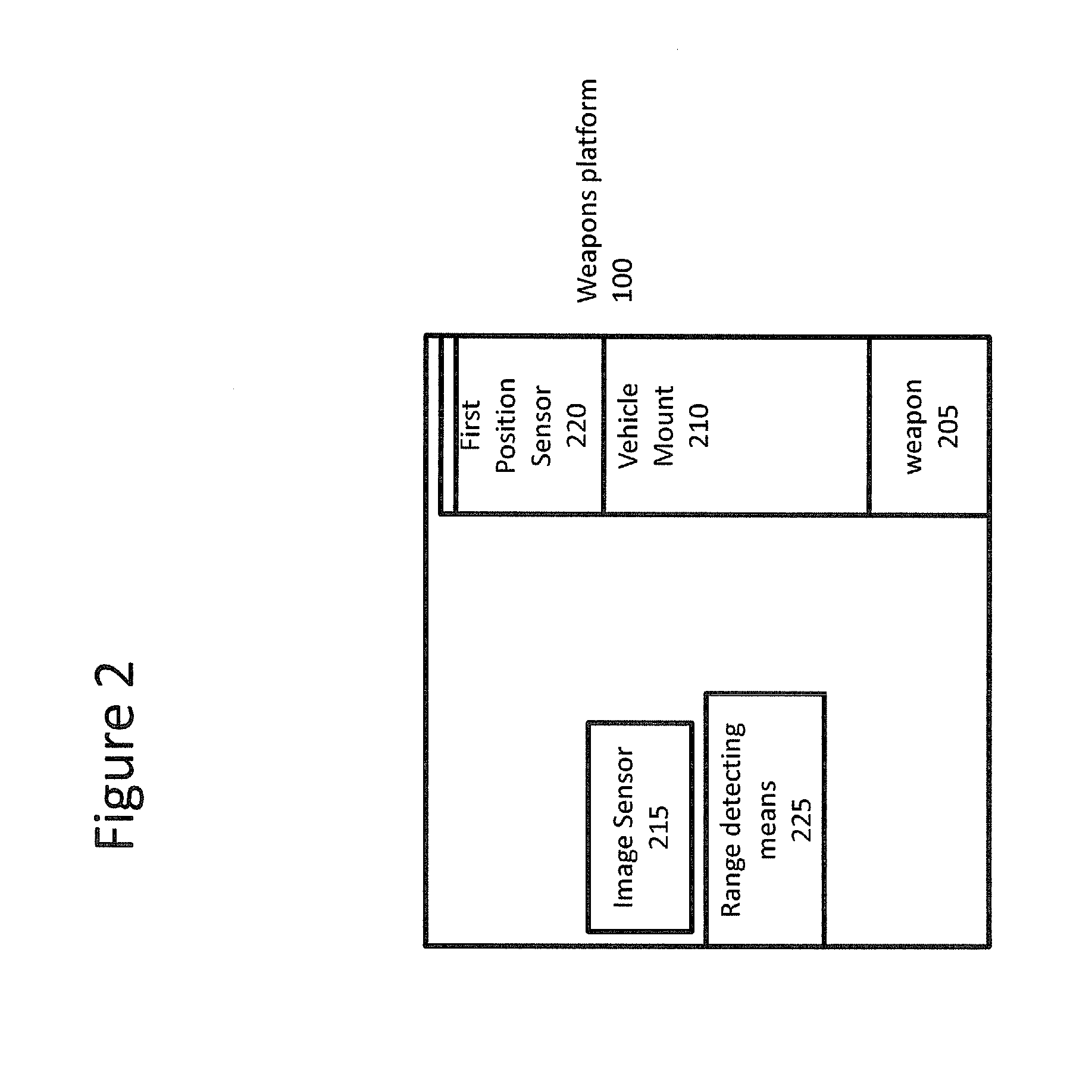
The patent describes a weapon system that allows a gunner to identify threats at longer ranges, increase accuracy, and improve lethality. The system includes a weapons platform with a gun that is attached to a moveable vehicle. It includes sensors to detect the position of the gun, the rate and altitude of the vehicle, and the range of the gun to the target. An image processor processes the sensor data and a display shows the processed image with the expected impact point of the gun superimposed on it. The system can also include a global position device to determine the vehicle's position. The method involves sensing the image of a remote target, processing the image, sensing the position of the gun, and calculating the expected impact point. The expected impact point is displayed on the processed image with a different indicator than the one used for the range detection. The method also includes determining a gun bore line and displaying it on the processed image.

Problems solved by technology

However, the detection is limited to the range of the gunner's eyesight.
At night the problem of identifying enemy targets is even greater due to the fact that enemy combatants are aware of the limitations with Night Vision Goggles.

Method used


Image

  • Weapons system and targeting method
  • Weapons system and targeting method
  • Weapons system and targeting method

Examples


Embodiment Construction

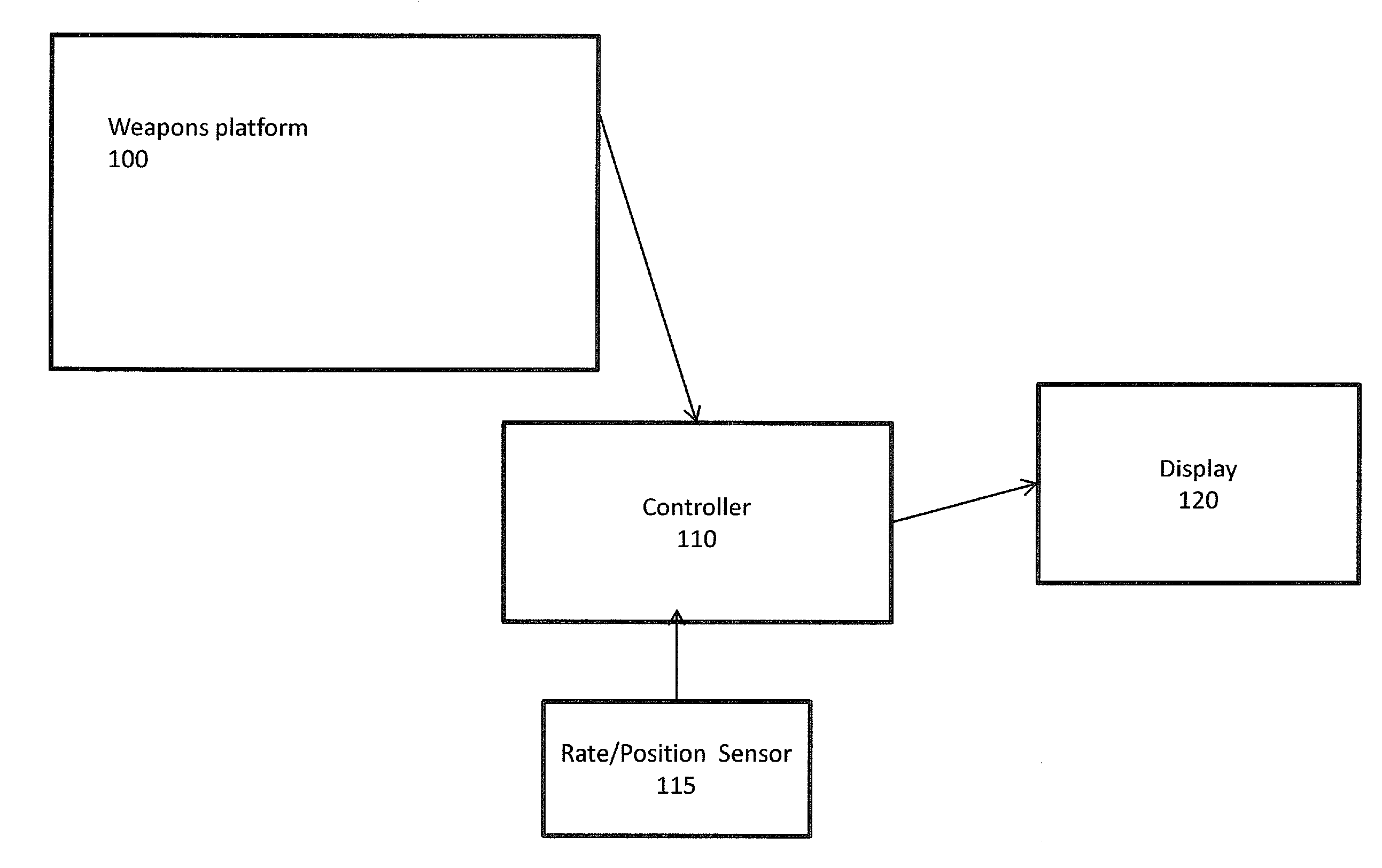
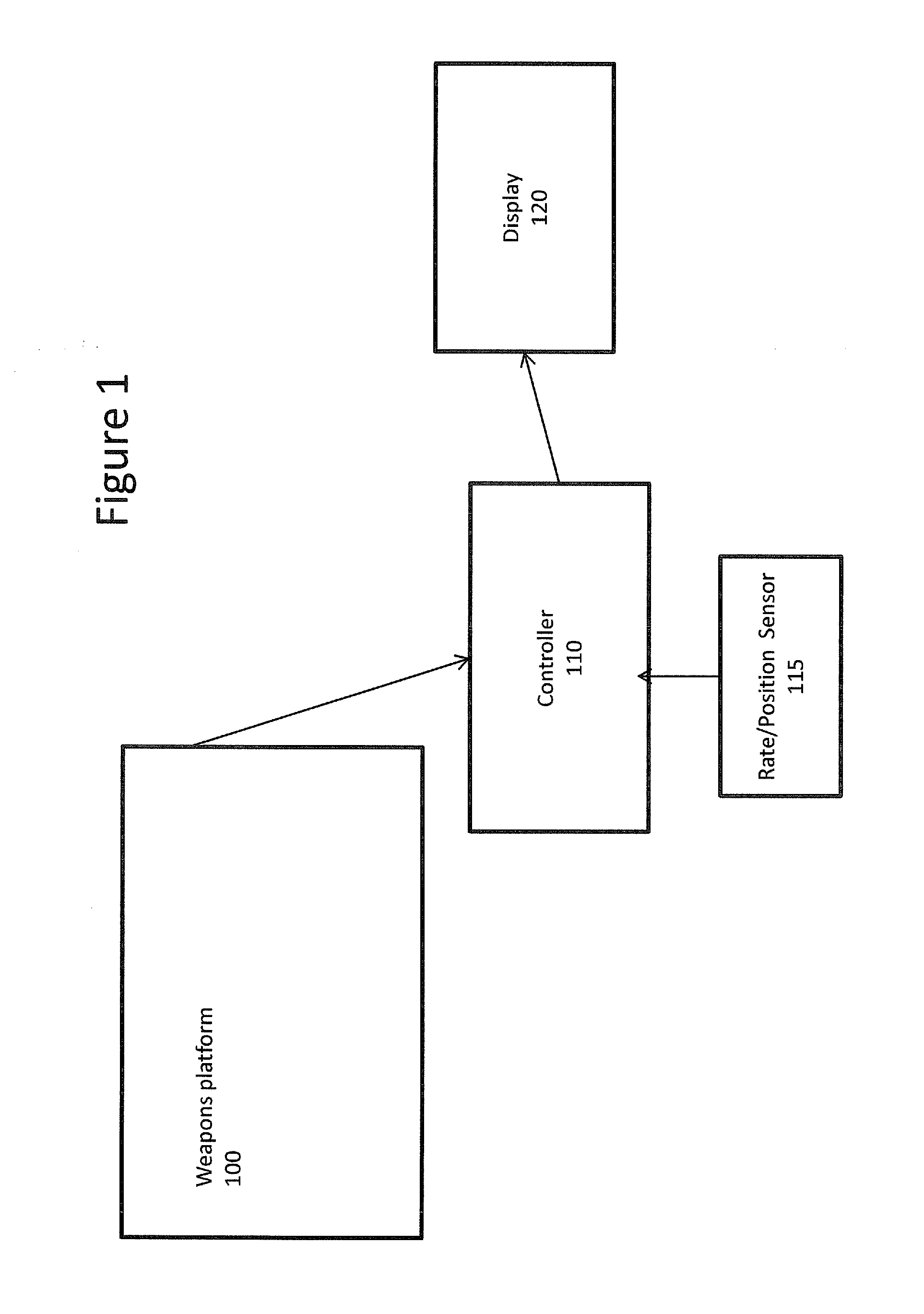
[0022]FIG. 1 depicts a weapons system 1 according to the invention. The weapons system 1 both detects an image and calculates an estimated or expected impact point for a round of fire or munitions and displays the image, an estimated or expected impact point and actual position of the weapon. Notably, the actual position of the weapon is superimposed over the image on a display using a first indicator. The estimated or expected impact point is superimposed over the image on the display using a second indicator. The weapons system 1 is adapted to be mounted or attached to a moving vehicle. The moving vehicle can be any land, air or water vehicle such as, but not limited to an ATV, tank, motorcycles, hovercraft, car, airplane, helicopter and ship.

[0023]The weapons system 1 includes a weapons platform 100, a controller 110, a rate / position sensor 115 and a display 120. The display 120 is responsive to signals from and controller 110. The weapons platform 100 contains weapon 205 and a v...


PUM


Abstract

A weapon system comprises a first, second and third sensor and a range detecting means. The weapon system further comprises a weapons platform removably mounted to a moveable vehicle. The weapons platform includes a gun. The first sensor is mechanically attached to the gun for sensing an image. The second sensor senses a position of the gun, including at least an elevation and azimuth. The third sensor detects a rate and altitude of the moveable vehicle. The range detecting means detects a range of the gun to the target. The weapon system also comprises an image processor for processing the image from the first sensor, a display for displaying the processed image and a controller. The controller calculates an expected impact point for a round of fire based upon the sensed and detected data, and superimposes the expected impact point on the processed image on the display.

Description

FIELD OF THE INVENTION[0001]This invention relates to a manned weapon system and targeting method for a manned weapon system.BACKGROUND[0002]Typical weapons systems are comprised of a weapon mounted onto a mount to a moving vehicle that allows the operator to slew the weapon in elevation and azimuth. These systems can be used to provide defensive suppression fire. Additionally, many of these systems, when employed from airborne platforms, can be used to provide close air support (CAS) where accuracy is extremely important due to the close proximity of friendly forces to enemy combatants.[0003]A typical system is operated by a single gunner whom identifies and locates a threat through unaided vision. At night, this is accomplished usually using Night vision Goggles. However, the detection is limited to the range of the gunner's eyesight. At night the problem of identifying enemy targets is even greater due to the fact that enemy combatants are aware of the limitations with Night Visi...

Claims


Application Information

Patent Timeline
Patent Type & Authority Applications(United States)
IPC IPC(8): G06G7/80
CPCF41G3/06F41G3/22F41G3/165
Inventor WEAVER, CHRISTOPHER S.
Owner BAE SYSTEMS CONTROLS INC
Learn More