Time domain electromagnetic interference monitoring method and system

a time domain electromagnetic interference and monitoring method technology, applied in the field of time domain electromagnetic interference monitoring methods and systems, can solve the problems of poor frequency response, large frequency band bandwidth, and inability to accurately represent wideband chaotic emi signals, etc., and achieve the effect of wide frequency band bandwidth

Active Publication Date: 2012-05-24
ESKOM HLDG
View PDF2 Cites 13 Cited by
  • Summary
  • Abstract
  • Description
  • Claims
  • Application Information

AI Technical Summary

Benefits of technology

[0014]The EMI spectrum produced may advantageously be substantially similar to an EMI spectrum that would be produced with an EMI receiver.
[0015]Each iteration may use time domain captures achieved with different configurations of capturing hardware. This may advantageously allow a final result covering a wider bandwidth of frequencies than would otherwise be achievable.

Problems solved by technology

Additionally, depending on the method of acquisition, the associated spectra of these signals may be polluted by components from extraneous sources.
These types of devices are relatively expensive and proper representation of wideband chaotic EMI signals requires the implementation of very long scan times when using these frequency domain acquisition devices.
The high cost of these devices and the long scan times required conspire against the practicality of widely deploying on-line real-time monitoring systems based on these acquisition options.

Method used


Image

  • Time domain electromagnetic interference monitoring method and system
  • Time domain electromagnetic interference monitoring method and system
  • Time domain electromagnetic interference monitoring method and system

Examples


Embodiment Construction

[0060]In the following description, for purposes of explanation, numerous specific details are set forth in order to provide a thorough understanding of an example embodiment of the present disclosure. It will be evident, however, to one skilled in the art that the present disclosure may be practiced without these specific details.

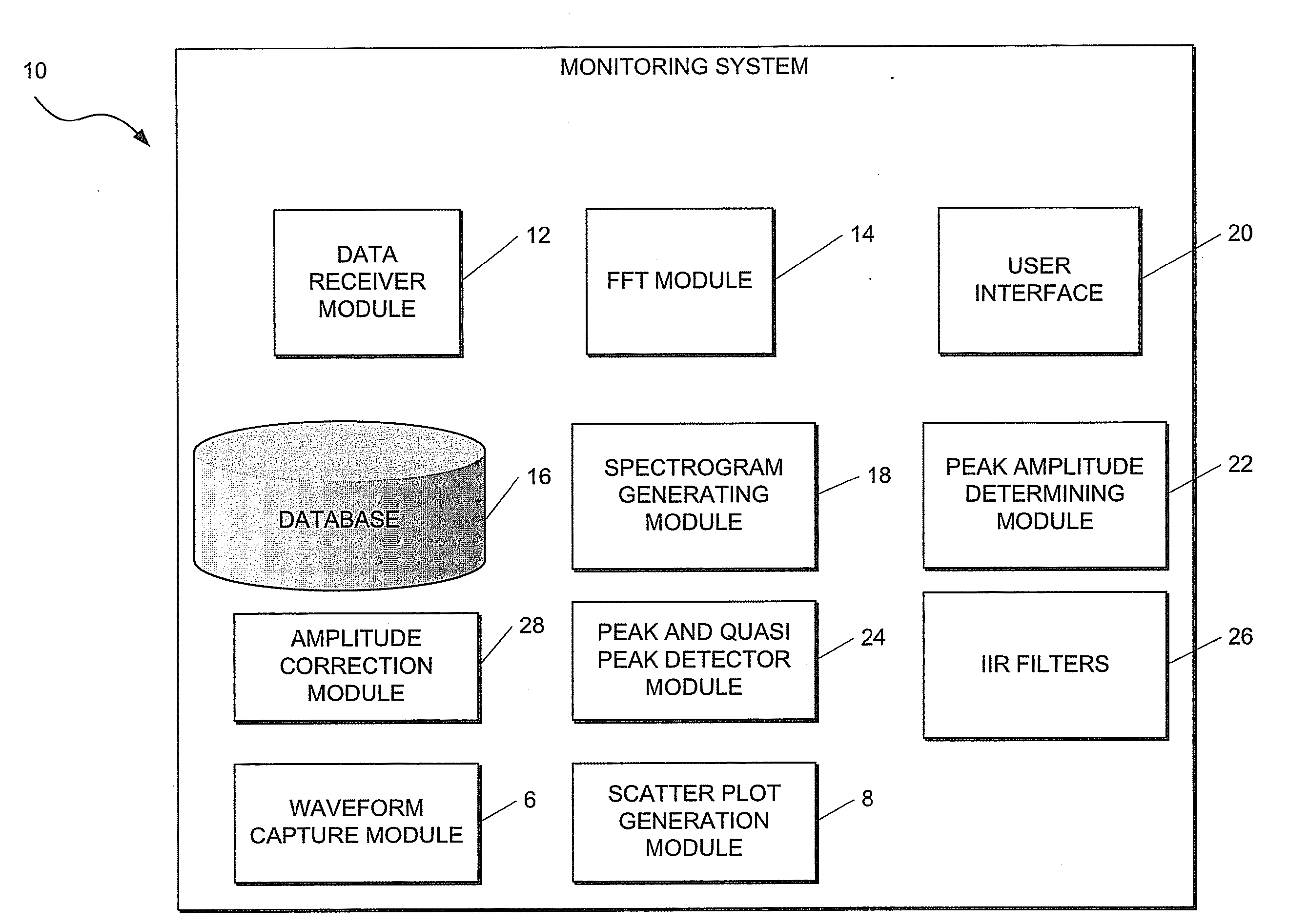
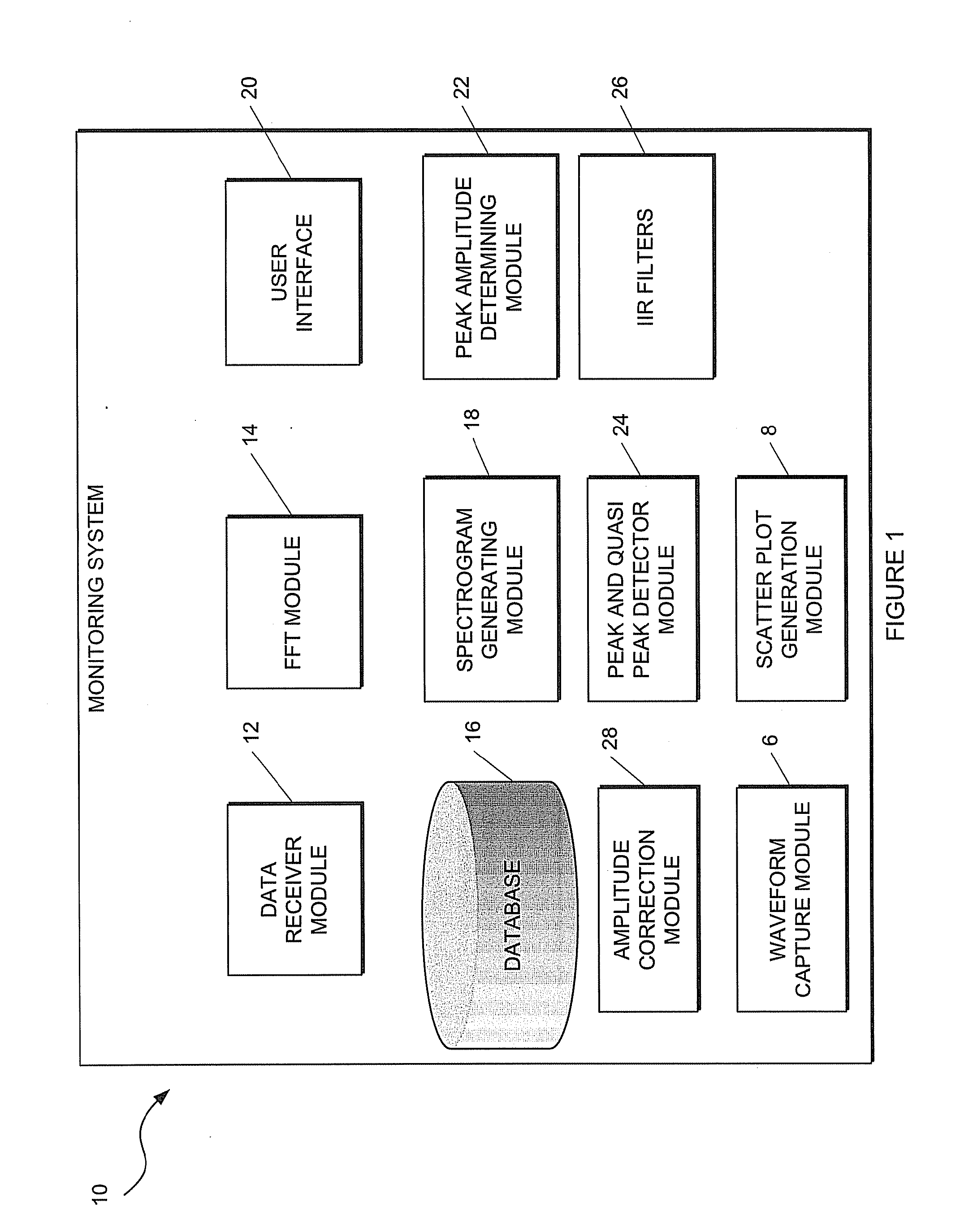
[0061]Referring now to FIG. 1 of the drawings where a system for monitoring electromagnetic interference (EMI) emitted by equipment in accordance with an example embodiment is generally indicated by reference numeral 10.

[0062]The system 10 typically comprises a plurality of components or modules which correspond to the functional tasks to be performed by the system 10. In this regard, “module” in the context of the specification will be understood to include an identifiable portion of code, computational or executable instructions, data, or computational object to achieve a particular function, operation, processing, or procedure. It follows that a module ...


PUM


Abstract

This invention relates to a method of, and a system for, monitoring electromagnetic interference. The method comprising capturing a plurality of time domain waveforms, and a plurality of scatter plots; receiving the plurality of captured time domain waveforms and scatter plots; applying a fast fourier transform (FFT) to each of the received time domain waveforms as it is received thereby to receive FFT outputs; storing the FFT outputs in a database; generating a statistically representative spectrograph or spectrogram in the frequency domain based on at least the stored FFT outputs and scatter plots or data associated with the scatter plots, combining constituent FFTs of the statistically representative spectrograph or spectrogram in such a manner as to emulate the result that would be produced by an EMI (Electromagnetic Interference) receiver or spectrum analyser; and combining resultant outputs from a number of iterations of this process to produce a final result (EMI spectrum).

Description

BACKGROUND OF THE INVENTION[0001]THIS invention relates to a method of and a system for monitoring electromagnetic interference.[0002]Electromagnetic Interference (EMI) signals are emitted by most high voltage (HV) apparatus or equipment. These signals or emissions usually cover a wide bandwidth and are determined by, amongst other things, operating voltage, apparatus design and geometry, insulation class and condition. Additionally, depending on the method of acquisition, the associated spectra of these signals may be polluted by components from extraneous sources. Specifically, generator EMI spectra cover a bandwidth from very low frequencies up to about 1 GHz. The most important component of this band is from approximately 150 kHz to 250 MHz. The signals in this bandwidth typically approach true randomness and the discrepancy between peak (PK) and quasi-peak (QP) values can be as much as about 10 dB.[0003]EMI spectra are captured by way of frequency domain acquisition equipment f...

Claims


Application Information

Patent Timeline
Patent Type & Authority Applications(United States)
IPC IPC(8): G06F19/00G01R23/18G01R23/16
CPCG01R29/0892G01R29/0814G01R23/16
Inventor HIGGINS, SIMON
Owner ESKOM HLDG
Why Eureka
Try Eureka