
Combining 3D video and auxiliary data

Active Publication Date: 2012-05-17
KONINKLIJKE PHILIPS ELECTRONICS NV
View PDF42 Cites 58 Cited by
  • Summary
  • Abstract
  • Description
  • Claims
  • Application Information

AI Technical Summary

Benefits of technology

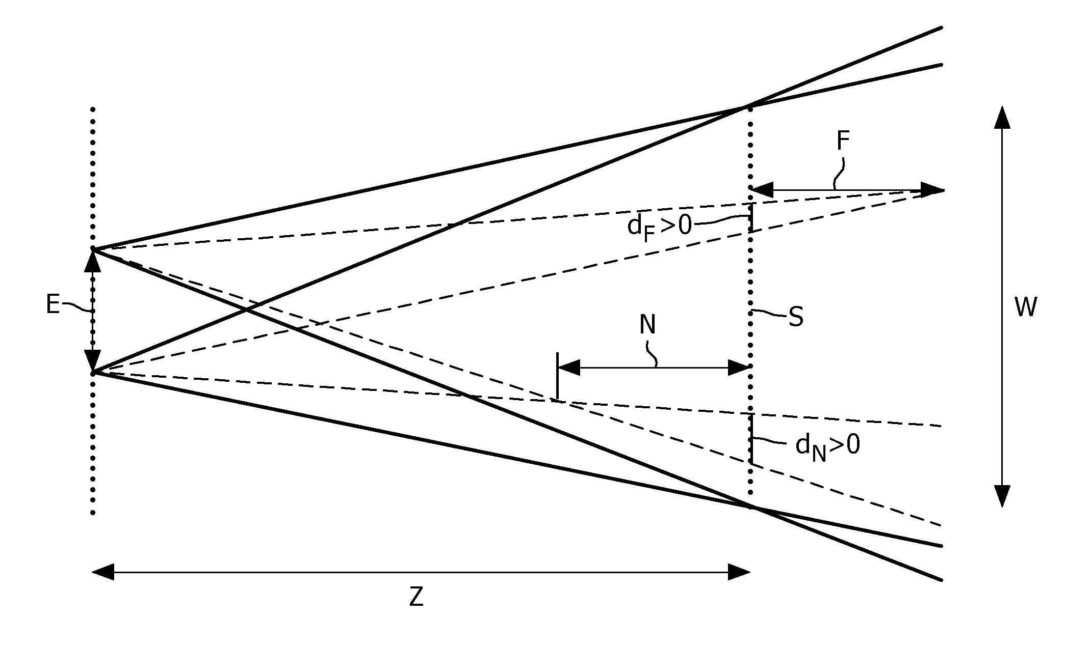
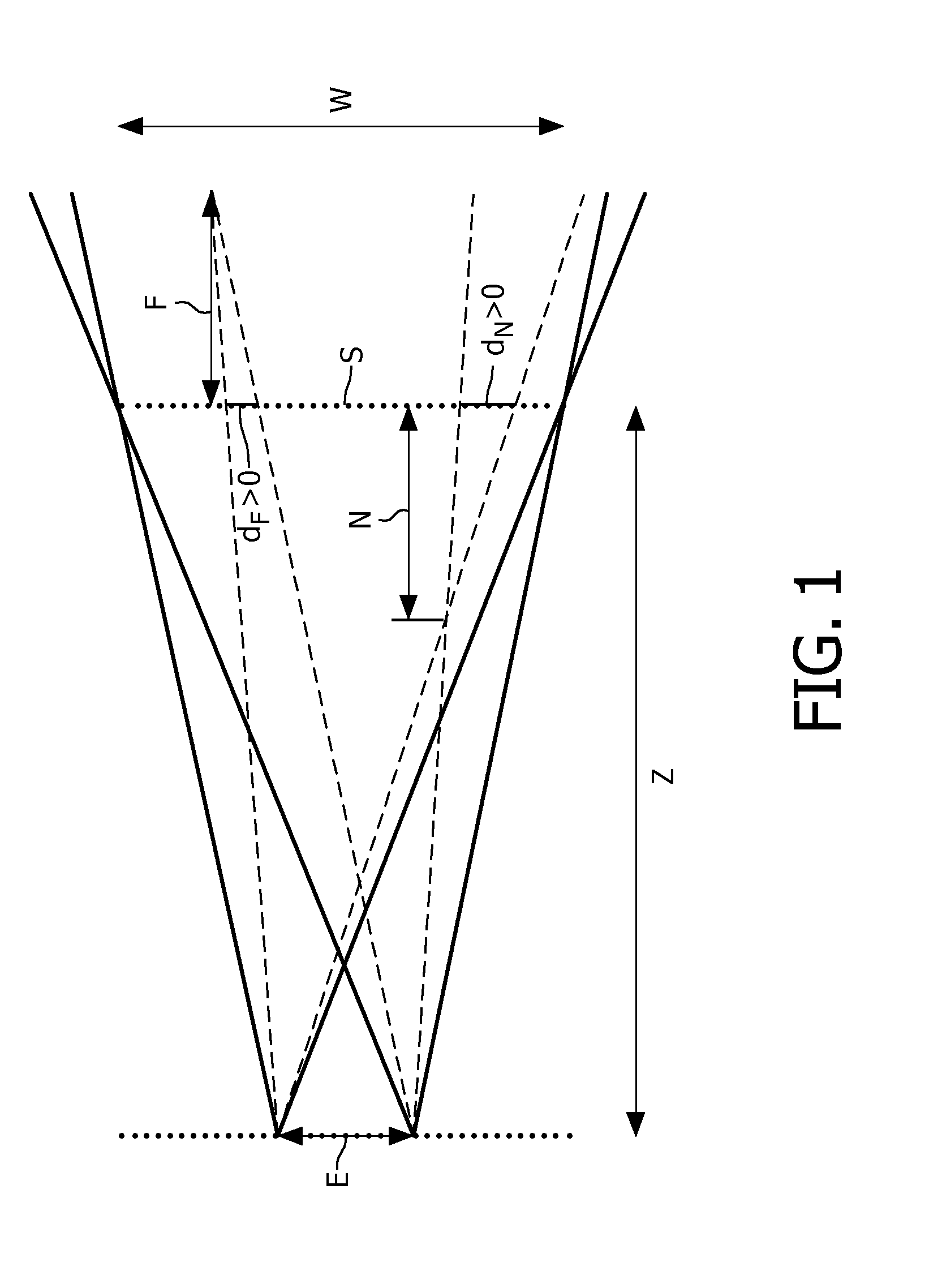
[0030]The measures have the effect of at the source determining depth values occurring in the 3D video data, e.g. calculating disparity values from left and right view in a left / right 3D format, or processing the depth data from a 2D+depth stream, or deriving such depth values from any other 3D image format. The depth metadata is subsequently included in the 3D video signal. Advantageously, at the destination device, any auxiliary data may be combined with the 3D video data, and positioned in the depth direction based on the depth metadata such that obscuring the auxiliary data by said nearest video data, and / or disturbing effects at the boundary of the auxiliary data, are avoided. It is noted that such disturbing effects would occur when auxiliary data is positioned farther away than a closer object but still would be displayed. In particular, the auxiliary data is not required to be available at the source device but is dynamically provided at the destination device which generates a combined 3D video signal by positioning the auxiliary data at the appropriate depth without requiring substantial processing resources for deriving the depth metadata.
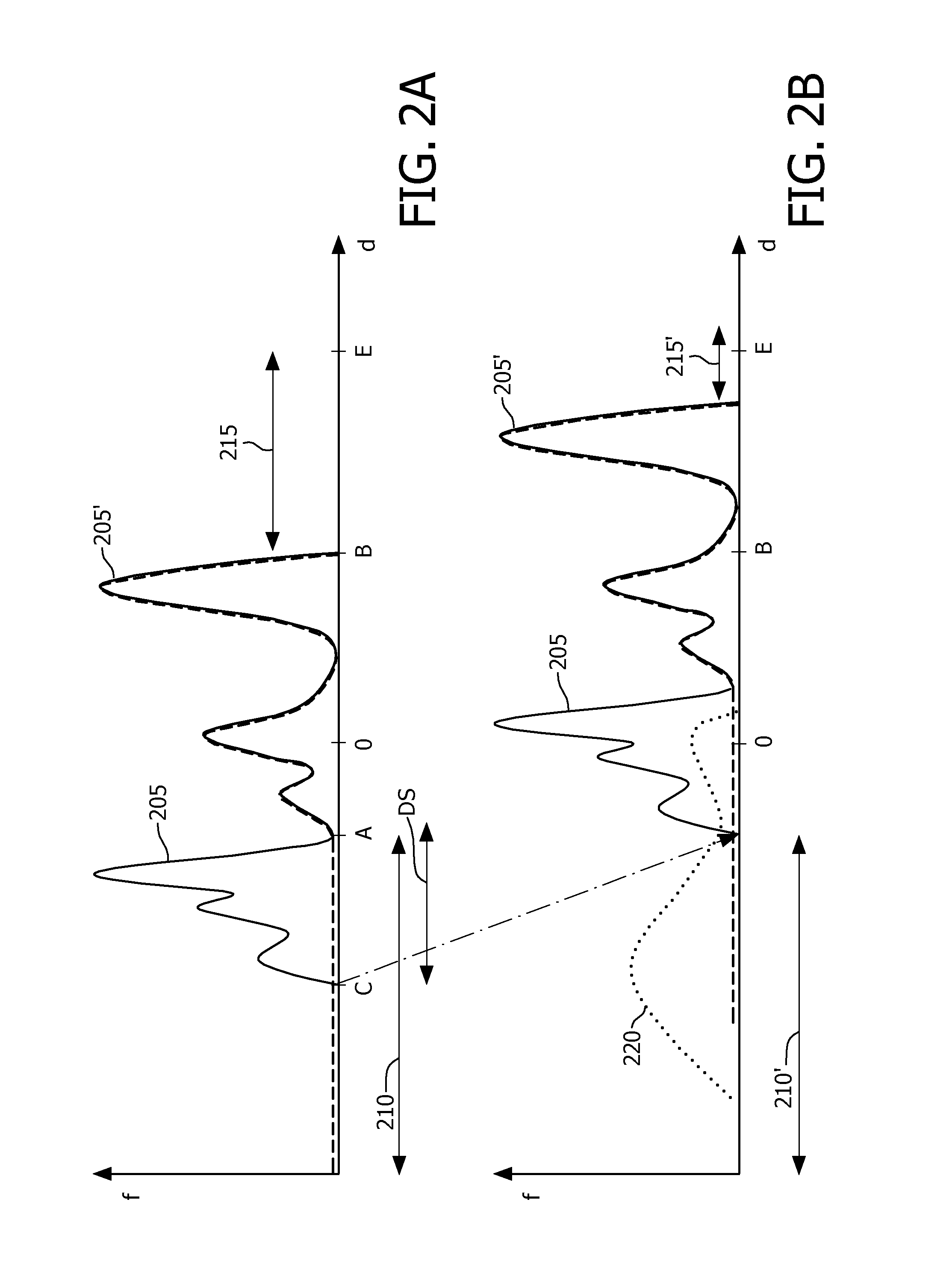
[0032]In an embodiment the depth metadata comprises a far value indicative of depths occurring in the 3D video data farthest away from the user for enabling the 3D destination device to set the auxiliary depth farther away from the user than the near value, and to apply a shift to the 3D video data in the direction away from the user for shifting said nearest video data to a depth farther away from the user than the auxiliary depth, the shift being maximized based on the far value. The effect is that the three dimensional video signal is adapted by shifting the input three dimensional video signal backwards (away from the viewer) by means of a shift in the depth direction based on the far value. Hence a range of depth is made free for positioning the auxiliary data in the depth direction in front of the shifted three dimensional video.
[0033]In an embodiment the near value is a disparity value. The effect is that the destination device is aware of the disparity value of the nearest video data, and can easily position auxiliary data before the video by using the disparity value. In an embodiment of the destination device, when the auxiliary data is two dimensional [2D] data and the near value is a disparity value, the processing means are arranged for generating at least a left auxiliary image and a right auxiliary image by applying, to the 2D auxiliary data, at least one horizontal shift based on the disparity value. Advantageously may be directly used to generate a right view by shifting a left view, or shifting the view by 50% of the disparity to the left and right to generate a left and right view.

Problems solved by technology

A problem occurs when auxiliary data needs to be combined with 3D video data in a destination device which has limited processing resources.

Method used


Image

  • Combining 3D video and auxiliary data
  • Combining 3D video and auxiliary data
  • Combining 3D video and auxiliary data

Examples


Embodiment Construction

[0055]It is noted that the current invention may be used for any type of 3D display that has a depth range. Video data for the 3D displays is assumed to be available as electronic, usually digital, data. The current invention relates to such image data and manipulates the image data in the digital domain.

[0056]There are many different ways in which 3D images may be formatted and transferred, called a 3D video format. Some formats are based on using a 2D channel to also carry the stereo information. For example the left and right view can be interlaced or can be placed side by side and above and under. These methods sacrifice resolution to carry the stereo information. Another option is to sacrifice color, this approach is called anaglyphic stereo. Anaglyphic stereo uses spectral multiplexing which is based on displaying two separate, overlaid images in complementary colors. By using glasses with colored filters each eye only sees the image of the same color as of the filter in front...


PUM


Abstract

A three dimensional [3D] video signal (41) is provided for transferring to a 3D destination device (50). Depth metadata is determined indicative of depths occurring in the 3D video data, which depth metadata includes a near value indicative of depths of video data nearest to a user. The 3D video signal, which comprises the 3D video data, now also includes the depth metadata. The 3D destination device (50) is enabled to retrieve the depth metadata, to provide auxiliary data, and to position the auxiliary data at an auxiliary depth in dependence of the retrieved metadata for displaying the auxiliary data in combination with the 3D video data such that obscuring the auxiliary data by said nearest video data, and / or disturbing effects at the boundary of the auxiliary data, is avoided.

Description

FIELD OF THE INVENTION[0001]The invention relates to a method of providing a three dimensional [3D] video signal for transferring to a 3D destination device, the method comprising determining depth metadata indicative of depths occurring in the 3D video data, which depth metadata includes a near value indicative of depths of video data nearest to a user.[0002]The invention further relates to a 3D source device, a 3D destination device, a signal, a record carrier and a computer program product.[0003]The invention relates to the field of rendering 3D video data in combination with auxiliary data such as subtitles, logos, or further 3D image data, on a 3D display device.BACKGROUND OF THE INVENTION[0004]Devices for generating 2D video data are known, for example video servers, broadcasters, or authoring devices. Currently 3D enhanced devices for providing three dimensional (3D) image data are being proposed. Similarly destination devices for rendering display 3D video data are being pro...

Claims


Application Information

Patent Timeline
IPC IPC(8): H04N13/04
CPCH04N13/0003H04N13/0048H04N13/0059H04N19/597H04N13/007H04N13/0425H04N13/0454H04N13/0066H04N13/359H04N13/10H04N13/161H04N13/178H04N13/183H04N13/194H04N13/327
Inventor NEWTON, PHILIP STEVENBOLIO, DENNIS DANIEL ROBERT JOZEFKURVERS, MARK JOZEF MARIAVAN DER HEIJDEN, GERARDUS WILHELMUS THEODORUSBRULS, WILHELMUS HENDRIKUS ALFONSUSDE HAAN, WIEBETALSTRA, JOHAN CORNELIS
Owner KONINKLIJKE PHILIPS ELECTRONICS NV
Learn More