Method for the welding production of a large-dimensioned part from ductile iron by using laser-deposition-welded buffer materials and electric welding

a technology of buffer materials and laser deposition welding, which is applied in the direction of manufacturing tools, soldering apparatus, superimposed coating process, etc., can solve the problems of compromising the strength of the steam turbine housing, inability to meet the requirements of welding, etc., to achieve the effect of high strength and large dimensions

Active Publication Date: 2012-05-17
SIEMENS ENERGY GLOBAL GMBH & CO KG
View PDF7 Cites 0 Cited by
  • Summary
  • Abstract
  • Description
  • Claims
  • Application Information

AI Technical Summary

Benefits of technology

[0008]According to the invention, the part components are combined in a two-stage welding process, the buffer material first being deposited onto the rim edges prepared as weld bead flanks. The buffer material has a high nickel content and is adapted to the ductile iron and to the method for welding the rim sections. A large-area connecting weld of the ductile iron parts is made possible by the two-stage process. This welded connection has mechanical properties which are advantageously similar to those of the ductile iron. The part can therefore be designed with large dimensions, the part being constructed from small part components which are not critical in terms of casting technology. The likelihood of unacceptable irregularities and defects in the part is therefore low, and production of the large-dimensioned part is made possible.
[0010]The buffer material is preferably deposited containing nickel and / or in a plurality of layers. This creates a tempering effect of the layer respectively deposited previously or the thermal influence zone in the material of the part component. A laser powder deposition welding method is preferably used for the deposition welding. It is particularly preferable that a laser powder deposition welding method is used for the deposition welding of the buffer material onto the first part component and a low-energy shield gas welding method is used for the deposition welding of the buffer material onto the second part component, in such a way that no thermal influence zone is formed on the rim sections. In this way, the buffer material can be deposited onto the part components with a minimal effect on the material of the part components, as a result of which advantageous mechanical properties are achieved in the thermal influence zone of the deposition welding of the powder material.

Problems solved by technology

The geometrical dimensions of a steam turbine in the upper power range, as are used for example for generating electricity in steam power plants, are however so large that problems can occur when casting ductile iron.
For example, there is a high likelihood that nonuniformities and defects will occur in such a steam turbine housing, which compromise the strength of the steam turbine housing.
Depending on the position in the part and the function of the positions affected, these nonuniformities and defects may be intolerable.
However, no manufacturing method is known by which these types of large-area welded connections of ductile iron can be produced.
In general, nonuniformities and defects always occur in cast parts produced from ductile iron.
However, the cold welding method produces a welded connection whose strength is less than the strength of the ductile iron.
The cold welding method is therefore unsuitable for large-area welded connections.
Hot welding is therefore very complicated and generates distortion of the part, so that hot welding is unsuitable for large-area connection welding of ductile iron.

Method used


Image

  • Method for the welding production of a large-dimensioned part from ductile iron by using laser-deposition-welded buffer materials and electric welding
  • Method for the welding production of a large-dimensioned part from ductile iron by using laser-deposition-welded buffer materials and electric welding
  • Method for the welding production of a large-dimensioned part from ductile iron by using laser-deposition-welded buffer materials and electric welding

Examples


Embodiment Construction

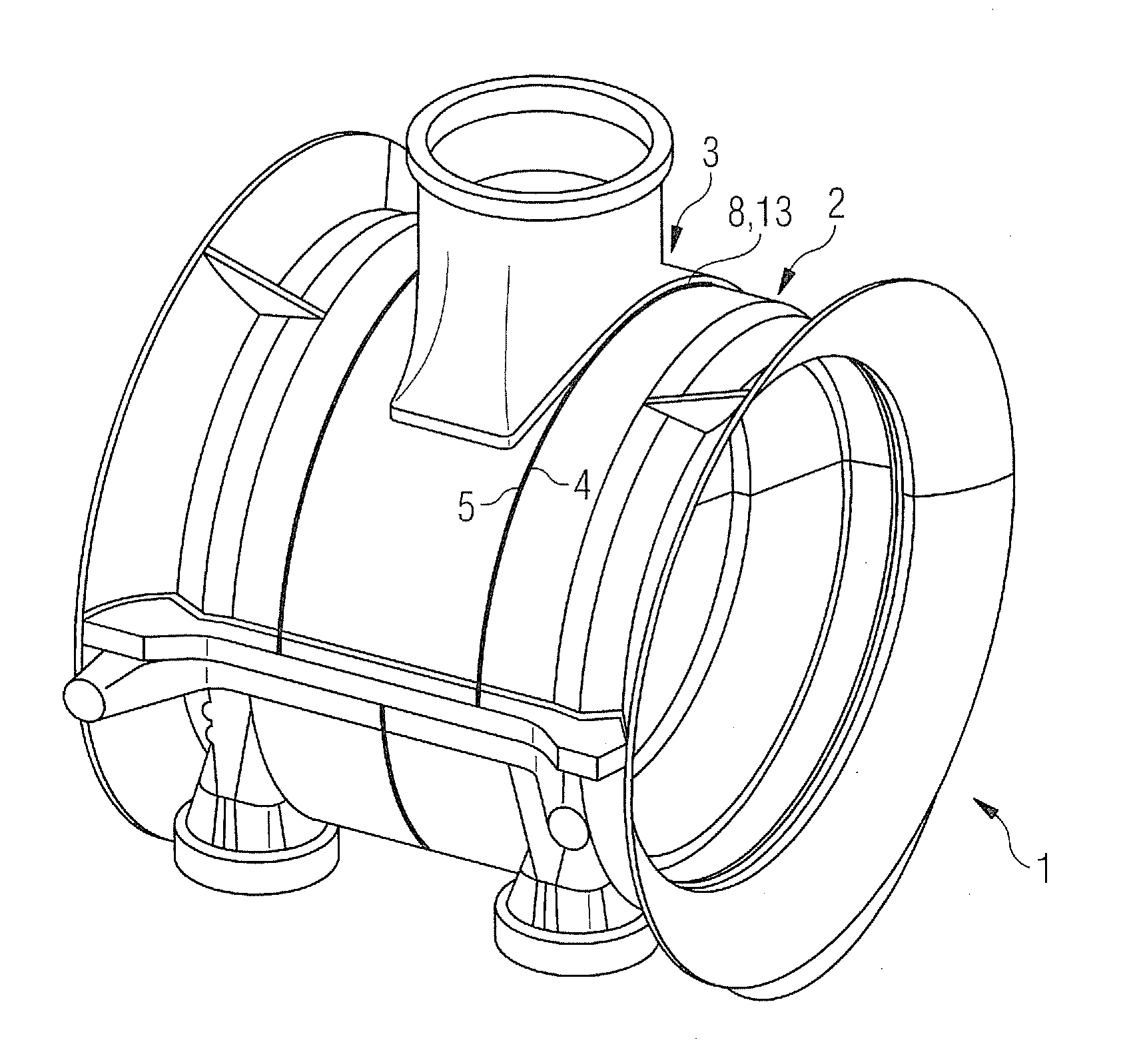
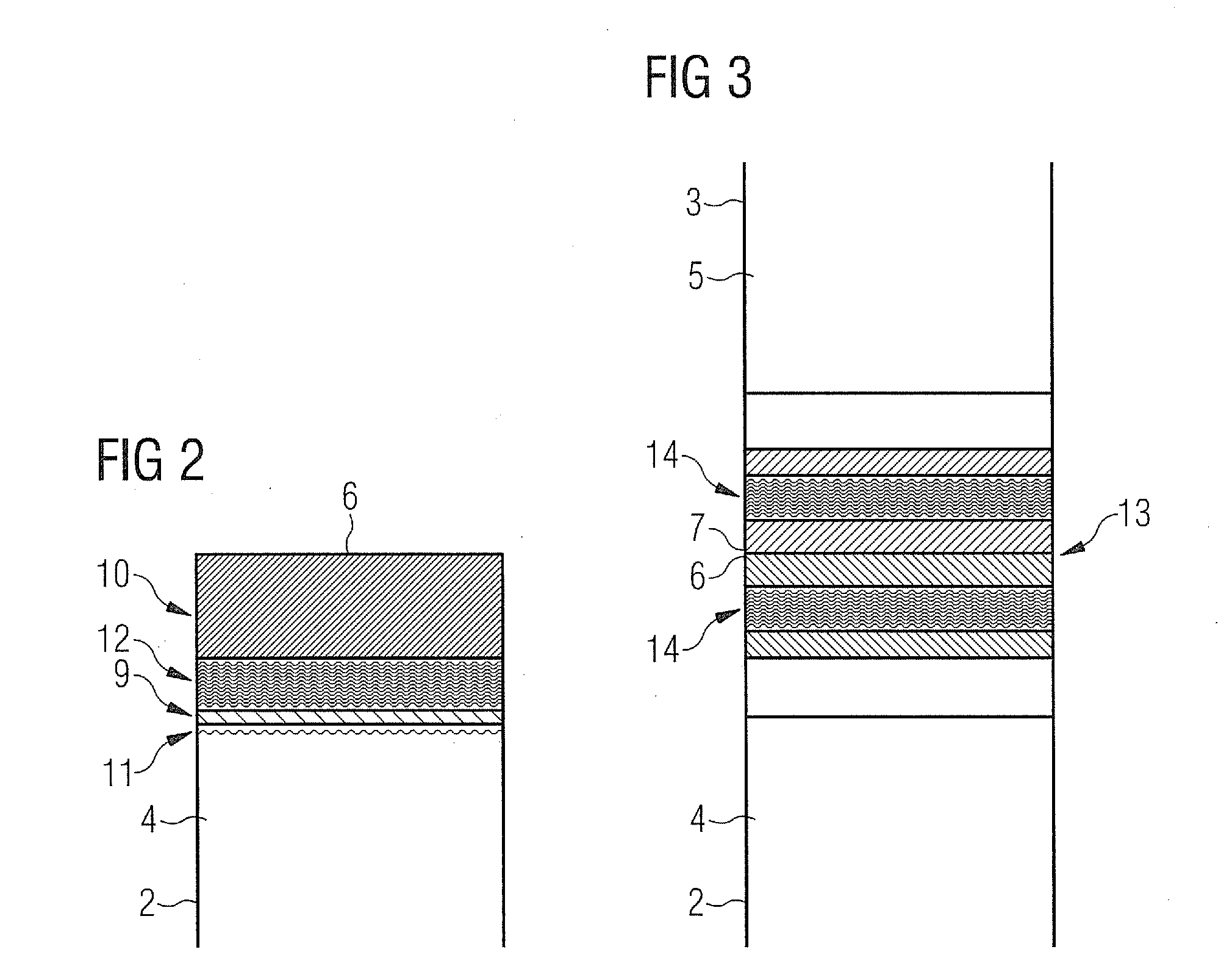
[0016]As can be seen in FIG. 1, a part is shown as a steam turbine low-pressure inner housing 1. The housing 1 is composed of a plurality of part components, in particular a first part component 2 and a second part component 3. The part components 2, 3 are placed on one another and form a partial joint 8. The part components 2, 3 are furthermore dimensioned and configured so that they can be cast from ductile iron without critical defects in their material.

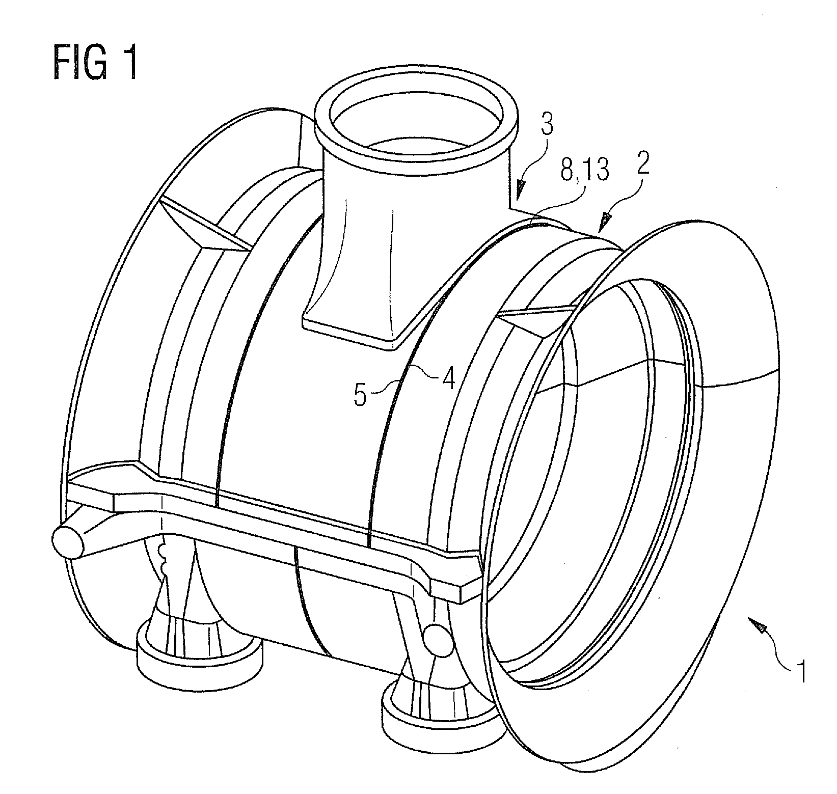
[0017]The first part component 2 comprises a rim section 4, which is arranged immediately next to a rim section 5 of the second part component 3. The rim section 4 of the first part component 2 is delimited by a rim edge 6 which bears flush on a rim edge 7 that delimits the rim section 5 of the second part component 3. The partial joint 8 is thereby formed by the rim edges 6, 7.

[0018]During production of the housing 1, the first part component 2 and the second part component 3 are produced separately from ductile iron in a ductile...


PUM

PropertyMeasurementUnit
Thicknessaaaaaaaaaa
Depthaaaaaaaaaa
Ductilityaaaaaaaaaa

Abstract

A method for producing a part from ductile iron, including the steps of designing the part in such a way that the part is composed of a plurality of part components, producing the part components from ductile iron, providing the part components in pairs, depositing buffer material onto the rim edge of the first part component and onto the rim edge of the second part component by means of deposition welding, laying the second part component with the rim section thereof on the rim section of the first part component so that the rim edges lie against each other with the buffer materials thereof, and welding the rim sections, wherein the buffer material is selected in such a way that a structure change in the ductile iron material of the part components is prevented when the rim sections are welded.

Description

CROSS REFERENCE TO RELATED APPLICATIONS[0001]This application is the US National Stage of International Application No. PCT / EP2010 / 054321, filed Mar. 31, 2010 and claims the benefit thereof. The International Application claims the benefits of European Patent Office application No. 09004999.0 EP filed Apr. 3, 2009. All of the applications are incorporated by reference herein in their entirety.FIELD OF INVENTION[0002]The invention relates to a method for the production of a large-dimensioned part from ductile iron.BACKGROUND OF INVENTION[0003]Ductile iron is a cast iron comprising spheroidal graphite, with which large-dimensioned parts can be mass-produced economically. For example, the housing of a steam turbine is conventionally manufactured from ductile iron. The geometrical dimensions of a steam turbine in the upper power range, as are used for example for generating electricity in steam power plants, are however so large that problems can occur when casting ductile iron. For exa...

Claims


Application Information

Patent Timeline
IPC IPC(8): B23K26/34
CPCB23K15/0073B23K35/0255B23K28/00B23K2201/001B23K2203/06C23C24/103C23C24/106C23C28/02C23C28/023F01D25/24F05D2230/233F05D2230/30B23K26/3206B23K26/345B23K35/3033B23K35/0244B23K15/0093B23K26/342B23K2101/001B23K2103/06B23K26/323B23K26/346
Inventor BRUSSK, STEFANGRUGER, BIRGITKRETSCHMER, MICHAELNIEPOLD, KARSTENSHENG, SHILUNWILHELM, CLAUS
Owner SIEMENS ENERGY GLOBAL GMBH & CO KG
Why Eureka
Try Eureka