
Method and system using a filter for treating exhaust gas having particulate matter

a technology of exhaust gas and filter, which is applied in the direction of machines/engines, metal/metal-oxide/metal-hydroxide catalysts, etc., can solve the problems of too soon to know whether particulate filtration will be necessary for the californian or us vehicle market generally, and a number of design problems, so as to promote surface filtration

Active Publication Date: 2012-05-03
JOHNSON MATTHEY PLC
View PDF6 Cites 28 Cited by
  • Summary
  • Abstract
  • Description
  • Claims
  • Application Information

AI Technical Summary

Benefits of technology

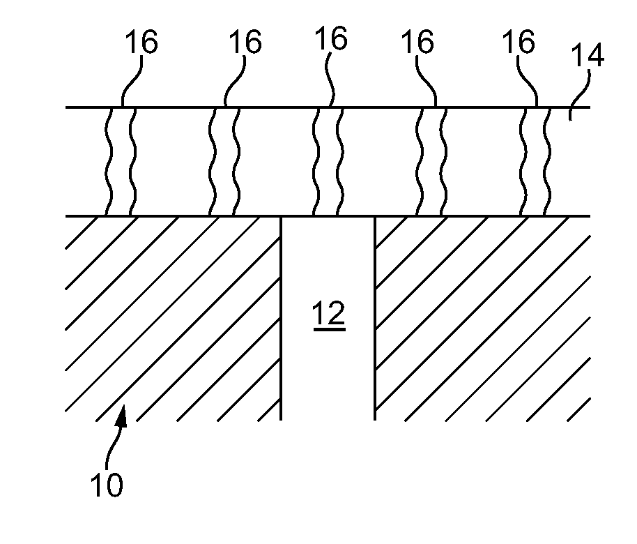
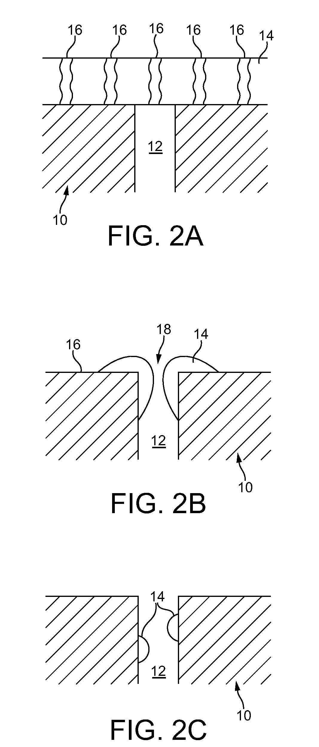
[0033]According to an embodiment of the invention, we have now discovered, very surprisingly, that it is possible to adapt a relatively porous particulate filter—such as a particulate filter adapted for a diesel application—so that it can be used to trap e.g. ultrafine positive ignition PM at an acceptable pressure drop and backpressure. In particular, our inventors have determined that a washcoat that hinders access of the PM to a porous structure of a filter substrate can beneficially promote surface filtration substantially at the expense of depth filtration to the extent that cake filtration of PM derived from a positive ignition engine is promoted or enhanced.

Problems solved by technology

Since the mid-1990's, particle size distributions of particulates exhausted from internal combustion engines have received increasing attention due to possible adverse health effects of fine and ultrafine particles.
However, since neither the PM standard nor the PM number standard has been set by CARB yet, it is too soon to know whether particulate filtration will be necessary for the Californian or US vehicle market generally.
The new Euro 6 emission standard presents a number of challenging design problems for meeting gasoline emission standards.
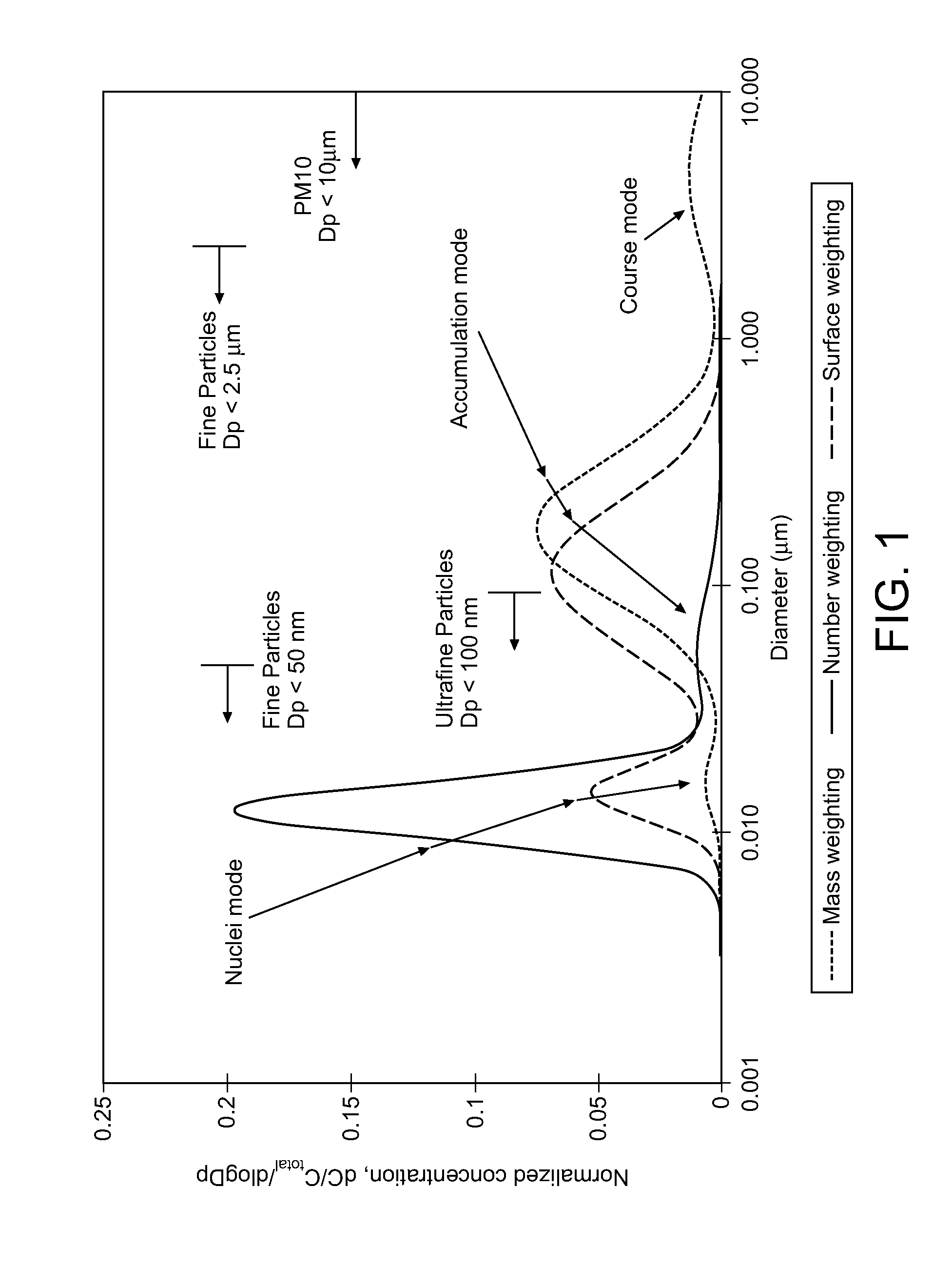
PM generated by positive ignition engines has a significantly higher proportion of ultrafine, with negligible accumulation and coarse mode compared with that produced by diesel (compression ignition) engines, and this presents challenges to removing it from positive ignition engine exhaust gas in order to prevent its emission to atmosphere.
In particular, since a majority of PM derived from a positive ignition engine is relatively small compared with the size distribution for diesel PM, it is not practically possible to use a filter substrate that promotes positive ignition PM surface-type cake filtration because the relatively low mean pore size of the filter substrate that would be required would produce impractically high backpressure in the system.
Furthermore, generally it is not possible to use a conventional wallflow filter, designed for trapping diesel PM, for promoting surface-type filtration of PM from a positive ignition engine in order to meet relevant emission standards because there is generally less PM in positive ignition exhaust gas, so formation of a soot cake is less likely; and positive ignition exhaust gas temperatures are generally higher, which can lead to faster removal of PM by oxidation, thus preventing increased PM removal by cake filtration.
Depth filtration of positive ignition PM in a conventional diesel wallflow filter is also difficult because the PM is significantly smaller than the pore size of the filter medium.
Another difficulty is combining filtration efficiency with a washcoat loading, e.g. of catalyst for meeting emission standards for non-PM pollutants, at acceptable backpressures.
However, we have found that washcoating a filter of this type at a sufficient catalyst loading such as is described in US 2006 / 0133969 to achieve required gasoline (positive ignition) emission standards can cause unacceptable backpressure.
However, we believe that the three-way catalyst washcoat loading of −3 provides insufficient three-way activity to meet the required emission standards alone, i.e. the claimed filter appears to be designed for inclusion in a system for location downstream of a three-way catalyst comprising a flowthrough substrate monolith.
For a majority of vehicle applications, this coated filter is unlikely to be able to meet the required emission standards alone.
A difficulty in coating a filter with a catalyst composition is to balance a desired catalytic activity, which generally increases with washcoat loading, with the backpressure that is caused by the filter in use (increased washcoat loading generally increases backpressure) and filtration efficiency (backpressure can be reduced by adopting wider mean pore size and higher porosity substrates at the expense of filtration efficiency).

Method used


Image

  • Method and system using a filter for treating exhaust gas having particulate matter
  • Method and system using a filter for treating exhaust gas having particulate matter
  • Method and system using a filter for treating exhaust gas having particulate matter

Examples


example 1

[0107]Two three-way catalyst (TWC) coatings were prepared at a washcoat loading of 2.4 g / in3 and a precious metal loading of 85 g / ft3 (Pd:Rh 16:1); one was milled to a small particle size (d90 <5 μm) that would be expected to pass into the pore structure of a wallflow filter (“in-wall”), while the other was less milled (d90 <17 μm) so that it would be expected preferentially to locate more at the surface of a wallflow filter wall (“on-wall”). The coatings were applied to 4.66×4.5 inch 300 cells per square inch cordierite wallflow filter substrates having 12 thousandths of an inch wall thickness (“300 / 12”) with a nominal average pore size of 20 micrometers (hereinafter “microns”) (62% porosity). Each filter was hydrothermally oven-aged at 980° C. for 4 hours and installed in a close-coupled position on a Euro 5 passenger car with a 1.4 L direct injection gasoline engine. Each filter was evaluated over a minimum of three MVEG-B drive cycles, measuring the reduction in particle number ...

example 2

[0111]5.66×3 inch cordierite wallflow filter substrates with a cell density of 300 cells per square inch and a wall thickness of 12 thousandths of an inch (approximately 0.3 mm) were coated with a three-way catalyst (TWC) coating at a washcoat loading of 0.8 g / in3 and a palladium loading of 80 g / ft3. Three pore structures were compared: a nominal average pore size of 38 microns at 65% porosity, a nominal average pore size of 20 microns at 62% porosity and a nominal average pore size of 15 microns at 52% porosity. Each filter was hydrothermally oven-aged at 980° C. for 4 hours and installed in the underfloor position on a Euro 4 passenger car with a 1.4 L direct injection gasoline engine, with a fully formulated three-way catalyst coated on a flowthrough substrate monolith located in the close-coupled position, i.e. upstream of the filter. Each filter was evaluated over a minimum of three MVEG-B drive cycles, measuring the reduction in particle number emissions relative to a referenc...

example 3

[0113]4.66×4.5 inch, 300 / 12 cordierite wallflow filter substrates with a nominal average pore size of 20 microns and porosity of 62% were coated with a three-way catalyst coating at washcoat loadings of 0.8, 1.6 and 2.4 g / in3 respectively. Each sample had a precious metal loading of 85 g / ft3 (Pd:Rh 16:1). Each filter was hydrothermally oven-aged at 980° C. for 4 hours and installed in a close-coupled position on a Euro 4 passenger car with a 1.4 L direct injection gasoline engine. Each filter was evaluated over a minimum of three MVEG-B drive cycles, measuring the reduction in particle number emissions relative to a reference catalyst, wherein the close-coupled filter was exchanged for a TWC coated on a flowthrough substrate monolith at an identical washcoat and precious metal loading, the backpressure differential and the conversion efficiency for gaseous HC, CO and NOx emissions were determined between sensors mounted upstream and downstream of the filter (or reference catalyst). ...


PUM

PropertyMeasurementUnit
densityaaaaaaaaaa
sizesaaaaaaaaaa
size distributionsaaaaaaaaaa

Abstract

A filter for filtering particulate matter (PM) from exhaust gas emitted from a positive ignition engine or a compression ignition engine, which filter comprising a porous substrate having inlet surfaces and outlet surfaces, wherein the inlet surfaces are separated from the outlet surfaces by a porous structure containing pores of a first mean pore size, wherein the porous substrate is coated with a washcoat comprising a plurality of solid particles wherein the porous structure of the washcoated porous substrate contains pores of a second mean pore size, and wherein the second mean pore size is less than the first mean pore size.

Description

CROSS-REFERENCE TO RELATED APPLICATIONS[0001]This application is a continuation-in-part of U.S. patent applications Ser. No. 12 / 712,681, filed on Feb. 25, 2010, which claims priority to GB Patent Application Nos. 0903262.4, filed on Feb. 26, 2009, and 0922612.7, filed on Dec. 24, 2009, and this application is a continuation-in-part of U.S. patent application Ser. No. 13 / 203,631, filed on Aug. 26, 2011, as the national stage application of International Application No. PCT / GB2010 / 050347, filed on Feb. 26, 2010, which claims priority to GB Patent Application Nos. 0903262.4, filed on Feb. 26, 2009, and 0922612.7, filed on Dec. 24, 2009, all of which are incorporated herein by reference in their entireties.FIELD OF THE INVENTION[0002]The present invention relates to a filter for use in treating particulate matter (PM) in exhaust gas derived from any combustion process, such as from a compression ignition engine or from a positive ignition engine. In an embodiment, the filter is used to ...

Claims


Application Information

Patent Timeline
Patent Type & Authority Applications(United States)
IPC IPC(8): B01D53/94
CPCB01J37/0246B01J23/464B01D53/9418B01D53/9422B01D53/9468B01D53/9477B01J29/06B01J29/061B01J29/082B01J29/088B01J29/126B01J29/146B01J29/166B01J29/405B01J29/44B01J29/46B01J29/505B01J29/54B01J29/56B01J29/7007B01J29/7057B01J29/7215B01J29/7415B01J29/7615B01J29/7815B01J35/023B01J35/04B01J35/10B01J35/1076B01J37/0036B01J37/0217F01N3/0842F01N3/2066F01N3/035B01D2255/2065B01D2255/20738B01D2255/20761B01D2255/50B01D2255/9155B01D2255/92B01D2255/9202B01D2258/012B01D2258/014B01D2275/30B01D2279/30F01N2310/06F01N2510/06Y02T10/24B01D53/9431B01D53/9409Y10S55/30Y02T10/12B01J35/56B01J35/60B01J35/40B01J35/657
Inventor ARNOLD, LOUISE CLAREBRISLEY, ROBERT JAMESMORGAN, CHRISTOPHER GOUGH
Owner JOHNSON MATTHEY PLC
Learn More