Eureka AIR delivers breakthrough ideas for toughest innovation challenges, trusted by R&D personnel around the world.

Functional imaging of cells with optical projection tomography

a technology of optical projection and functional imaging, applied in the field of optical projection tomography for functional microscopy, can solve the problems of permanent stop of fluorophores, inability to fix, stained live cells,

Active Publication Date: 2012-05-03
VISIONGATE
View PDF8 Cites 34 Cited by
  • Summary
  • Abstract
  • Description
  • Claims
  • Application Information

AI Technical Summary

Benefits of technology

[0012]This summary is provided to introduce a selection of concepts in a simplified form that are further described below in the Detailed Description. This summary i

Problems solved by technology

Live cells may be stained, but are usually not fixed.
Unfortunately, a common problem in fluorescence microscopy is photobleaching, in which some of the fluorophores permanently cease to emit light.
This can occur over time periods ranging from seconds to minutes, and results in a reduction of the signal level, with a concomitant decrease on the signal-to-noise ratio.
Another problem that can occur during FOPTM is poor focus.
Poor focus typically results from a focal-plane scan range that does not encompass the entire object thickness.
This focusing error yields an image with lower contrast between dark and light regions than would otherwise be obtained.
Yet another problem may be introduced by the presence of a gradient in the light intensity across the field of view.
A typical cause of this phenomenon is misalignment of the optical components in the camera system.
This need is exacerbated by the fact that fluorescence presents a problem for conventional tomography, since fluorescence is typically produced by a light source within the reconstruction volume, along the projection path.

Method used


Image

  • Functional imaging of cells with optical projection tomography
  • Functional imaging of cells with optical projection tomography
  • Functional imaging of cells with optical projection tomography

Examples


Embodiment Construction

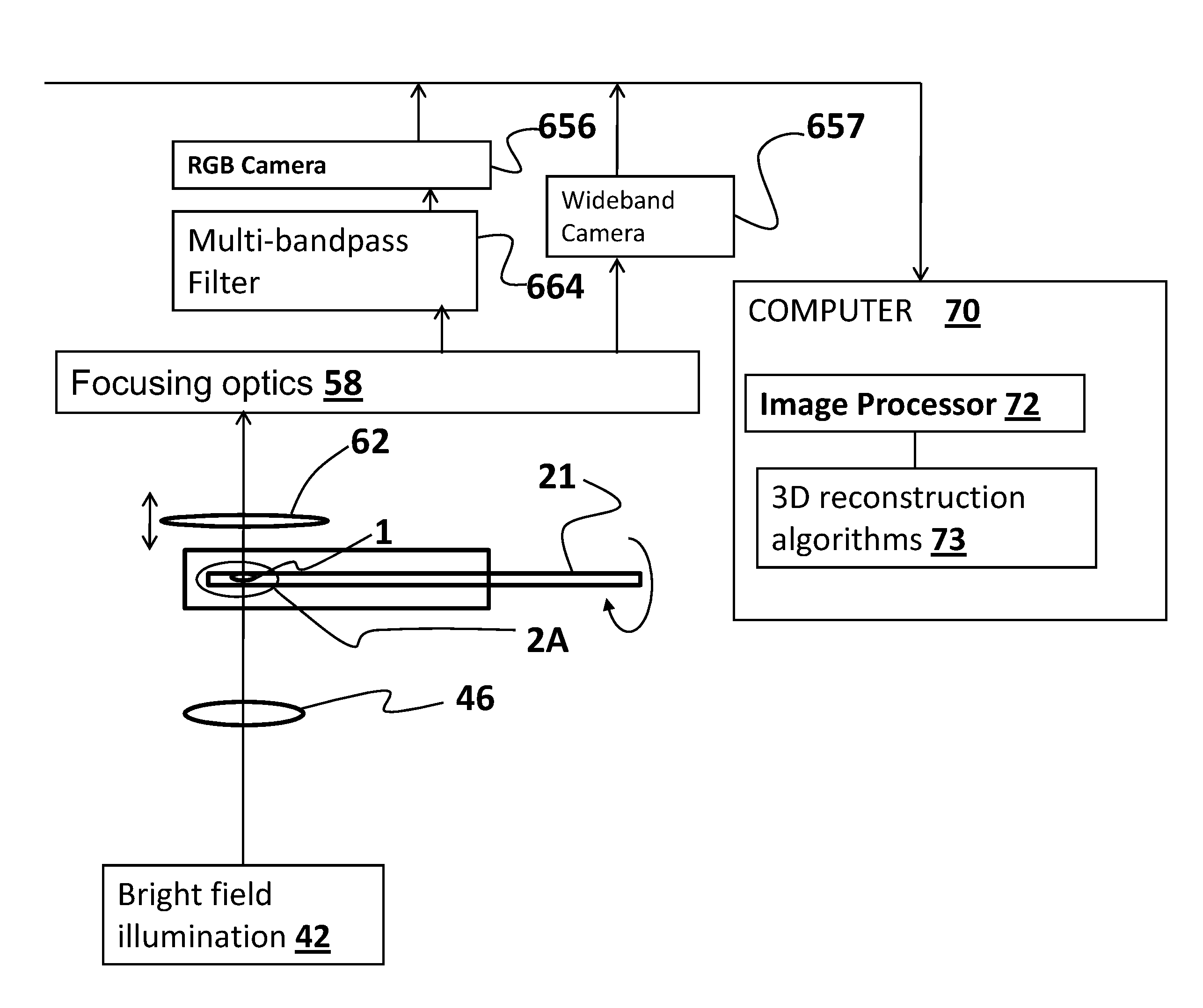
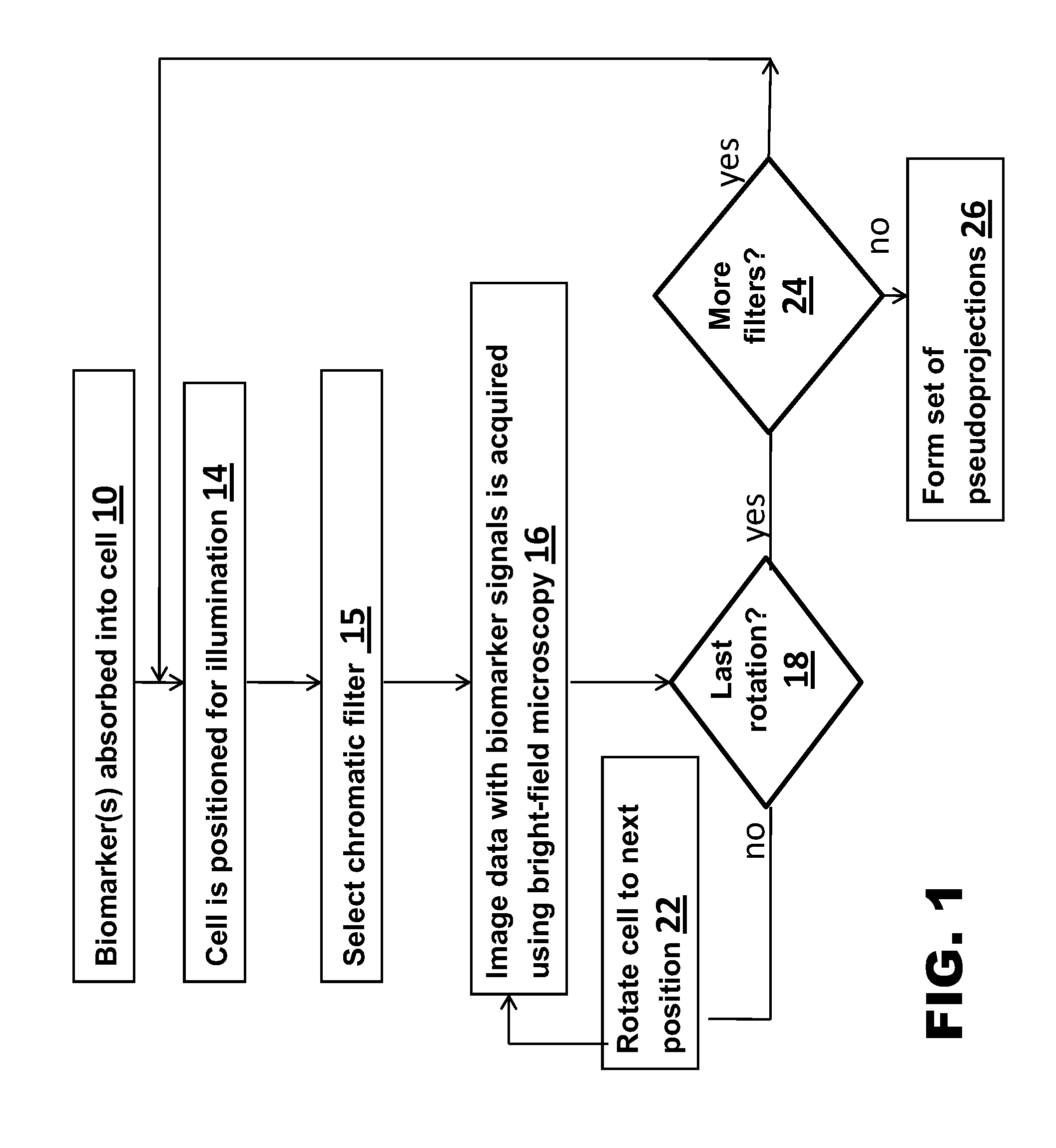
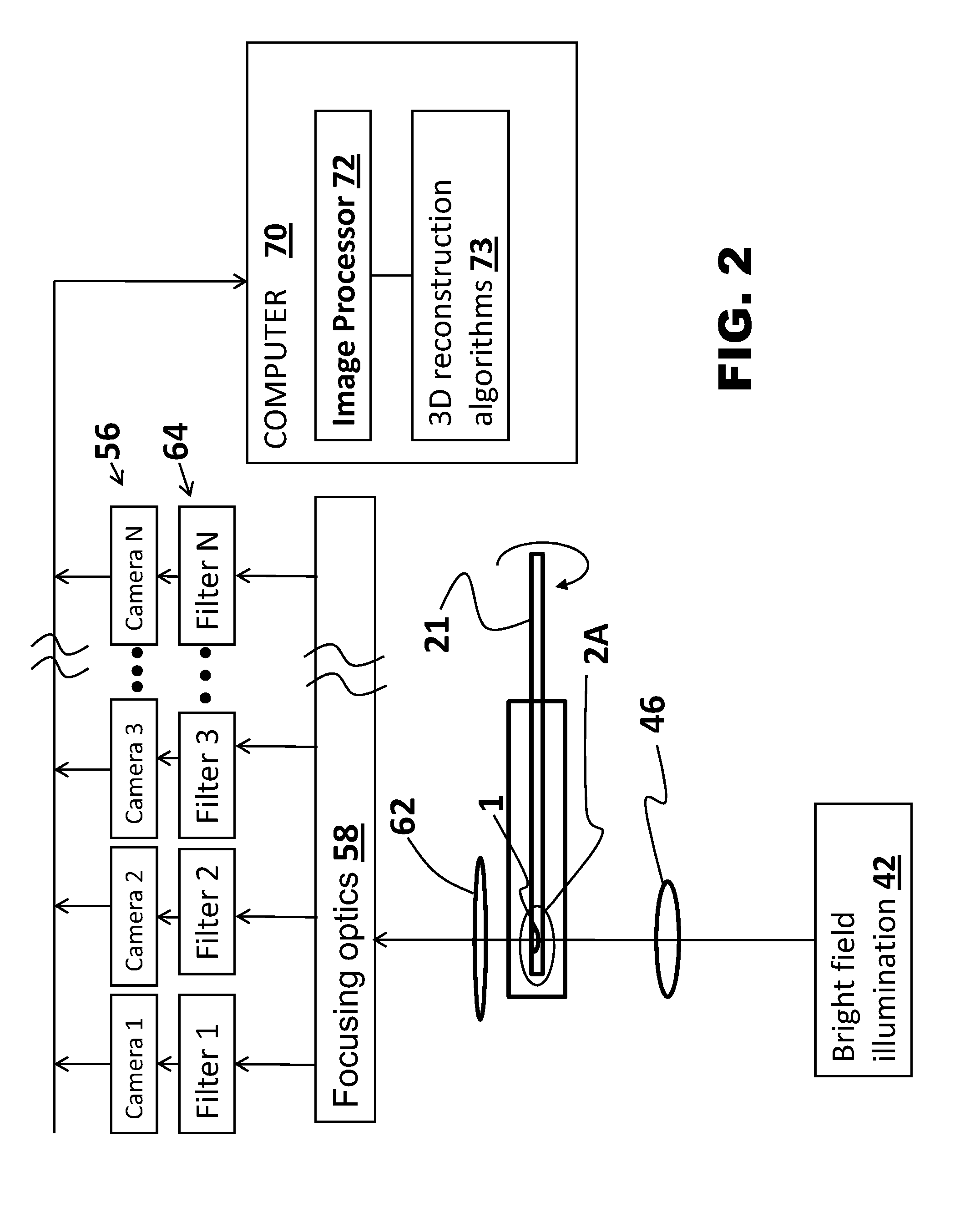
[0038]The following disclosure describes several embodiments and systems for imaging an object of interest. Several features of methods and systems in accordance with example embodiments are set forth and described in the Figures. It will be appreciated that methods and systems in accordance with other example embodiments can include additional procedures or features different than those shown in Figures. Example embodiments are described herein with respect to biological cells. However, it will be understood that these examples are for the purpose of illustrating the principles of the invention, and that the invention is not so limited.

[0039]Additionally, methods and systems in accordance with several example embodiments may not include all of the features shown in these Figures. Throughout the Figures, like reference numbers refer to similar or identical components or procedures.

[0040]Unless the context requires otherwise, throughout the specification and claims which follow, the ...


PUM


Abstract

A method for 3D imaging of a biologic object (1) in an optical tomography system where a subcellular structure of a biological object (1) is labeled by introducing at least one nanoparticle-biomarker. The labeled biological object (1) is moved relatively to a microscope objective (62) to present varying angles of view and the labeled biological object (1) is illuminated with radiation having wavelengths between 150 nm and 900 nm. Radiation transmitted through the labeled biological object (1) and the microscope objective (62) within at least one wavelength bands is sensed with a color camera, or with a set of at least four monochrome cameras. A plurality of cross-sectional images of the biological object (1) from the sensed radiation is formed and reconstructed to make a 3D image of the labeled biological object (1).

Description

RELATED APPLICATIONS[0001]This application hereby claims the benefit of prior filed co-pending U.S. provisional patent application No. 61 / 074,513, filed Jun. 20, 2008, of Rahn et al., entitled “Functional Imaging of Cells with Optical Projection Tomography,” which is incorporated herein by this reference, and also hereby claims the benefit of prior filed co-pending U.S. provisional patent application No. 61 / 150,286, filed Feb. 5, 2009, of Rahn et al., entitled “Method for Applying Mass Conservation to Fluorescent Optical Tomography,” which is also incorporated herein by this reference.TECHNICAL FIELD[0002]The present invention relates to optical tomography microscopy imaging systems in general, and, more particularly, to optical projection tomography for functional microscopy, in which a small object, such as a biological cell, is labeled and illuminated with optical radiation for imaging and reconstruction into a 3D image.BACKGROUND[0003]Advances in imaging biological cells using o...

Claims


Application Information

Patent Timeline
IPC IPC(8): H04N13/02
CPCG01N21/49G01N21/6458G06T11/006G01N15/1434G01N2015/1445G01N15/1433
Inventor MEYER, MICHAEL G.RAHN, J. RICHARDTOUROVSKAIA, ANNA V.YU, JULIA OI YANLANCASTER, CHRISTY A.NEUMANN, THOMASFAUVER, MARK E.
Owner VISIONGATE
Why Eureka
Eureka Blog
Learn More