
Apparatus and method for frame and brick constructions

a technology for installing bricks and apparatuses, which is applied in the field of apparatus and methods for constructing and installing bricks, and can solve the problems of brick edge protruding into the furnace, and affecting the quality of the finished produ

Active Publication Date: 2012-05-03
BERRY METAL
View PDF6 Cites 12 Cited by
  • Summary
  • Abstract
  • Description
  • Claims
  • Application Information

AI Technical Summary

Benefits of technology

[0020]These and other advantages of the invention will be appreciated by reference to the detailed description of the preferred embodiment(s) that follow.

Problems solved by technology

During furnace operation, the ram gap often erodes prematurely and furnace gases track between the staves.
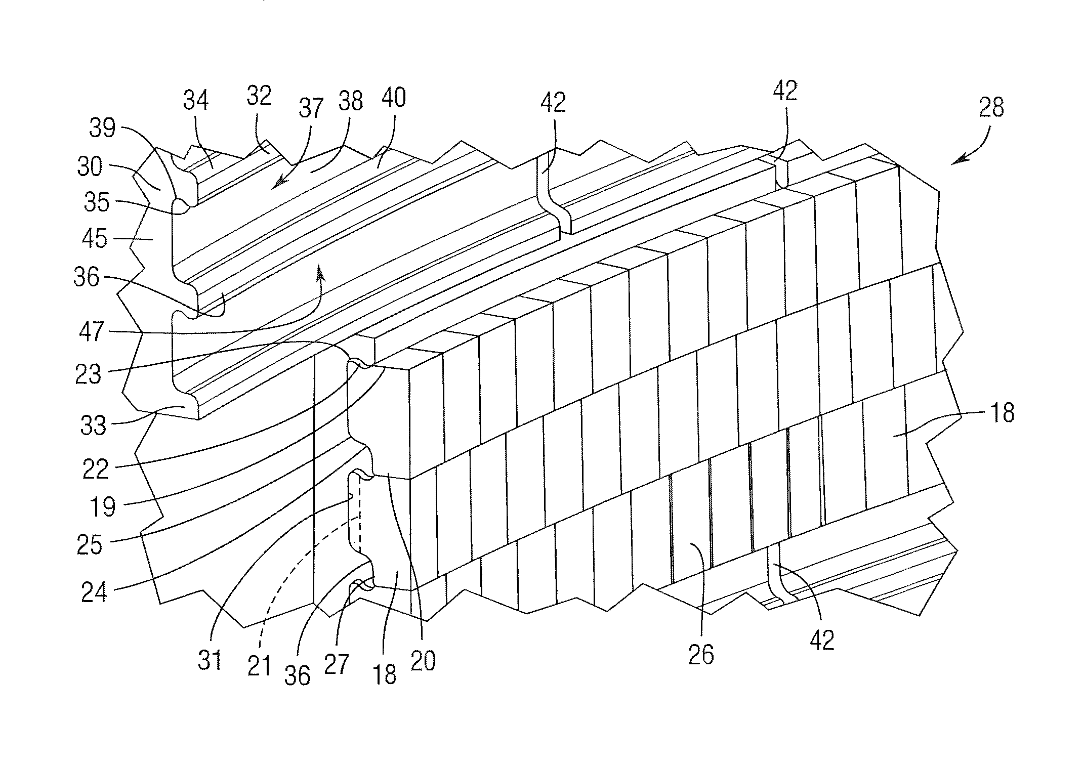
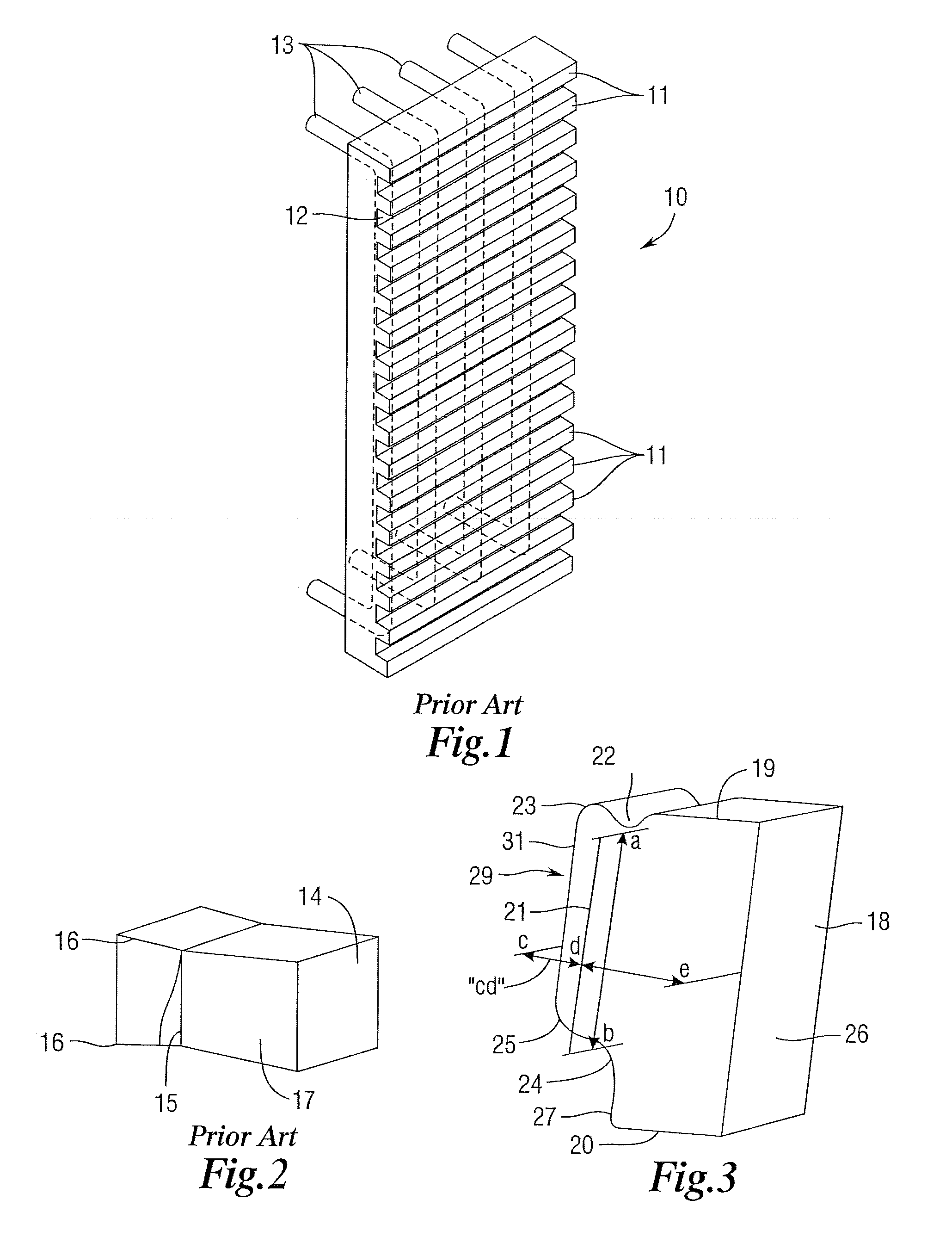
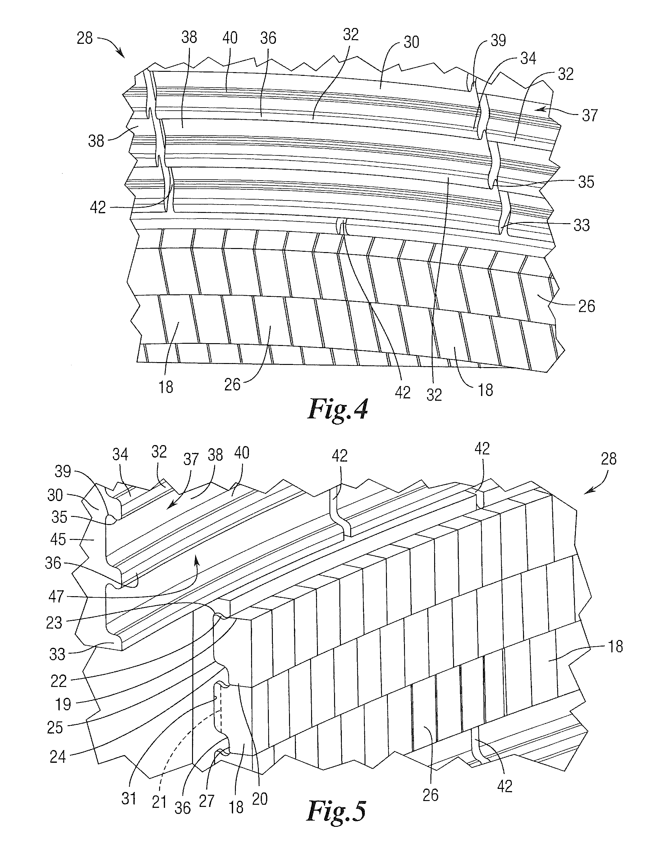
Moreover, such conventional stave / brick constructions leave brick edges protruding into the furnace which are exposed to matter and other debris falling through the furnace.
Such protruding brick edges tend to wear out more frequently than non-protruding edges, leading to broken or crumbled bricks that may fall through the furnace causing further damage to the furnace lining.
Such broken bricks also expose the stave thereby causing it to be damaged or worn out prematurely.
This process related skull is generated and lost repeatedly in service and actually changes furnace performance.
Therefore, this skull approach is not effective if the cohesive zone is incorrectly determined.
Additionally, the cohesive zone of the furnace changes depending on charge material and the skull adhesion is lost in sections of the furnace at different times. This results in non-uniform temperatures throughout the staves and furnace.
Such thin-necked bricks are susceptible to cracking at the thin neck portion thereby creating brick fragments and pieces falling into the furnace which may hit and damage other bricks and staves of the furnace lining.
Such constructions contain joints which further prevent effective cooling of the bricks farthest from the stave.

Method used


Image

  • Apparatus and method for frame and brick constructions
  • Apparatus and method for frame and brick constructions
  • Apparatus and method for frame and brick constructions

Examples


Embodiment Construction

[0063]In the following detailed description, reference is made to the accompanying examples and figures that form a part hereof, and in which is shown, by way of illustration, specific embodiments in which the inventive subject matter may be practiced. These embodiments are described in sufficient detail to enable those skilled in the art to practice them, and it is to be understood that other embodiments may be utilized and that structural or logical changes may be made without departing from the scope of the inventive subject matter. Such embodiments of the inventive subject matter may be referred to, individually and / or collectively, herein by the term “invention” merely for convenience and without intending to voluntarily limit the scope of this application to any single invention or inventive concept if more than one is in fact disclosed.

[0064]The following description is, therefore, not to be taken in a limited sense, and the scope of the inventive subject matter is defined by...


PUM

PropertyMeasurementUnit
Angleaaaaaaaaaa
Widthaaaaaaaaaa
Depthaaaaaaaaaa

Abstract

A frame / brick and / or a stave / brick construction, having a frame having a plurality of ribs and a plurality of channels, wherein a front face of the frame defines a first opening into each of the channels, and a plurality of bricks wherein each brick is insertable into one of the plurality of channels via its first opening to a position, upon rotation of the brick, partially disposed in the one channel such that one or more portions of the brick at least partially engage one or more surfaces of the one channel and / or of a first rib of the plurality of ribs whereby the brick is locked against removal from the one channel through its first opening via linear movement without first being rotated.

Description

CROSS REFERENCE TO RELATED APPLICATIONS[0001]This application claims the benefit of (1) provisional patent application U.S. Ser. No. 61 / 223,745 filed Jul. 8, 2009, by the present inventor, which is incorporated by reference herein and (2) provisional patent application U.S. Ser. No. 61 / 231,477 filed Aug. 5, 2009, by the present inventor, which is incorporated by reference herein.TECHNICAL FIELD OF THE INVENTION[0002]This invention relates generally to apparatus and methods for constructing and installing bricks, such as refractory bricks, in frames, staves and / or coolers in blast furnaces or other metallurgical furnaces. Related fields include systems and methods for cooling blast furnaces and other metallurgical furnaces. Related fields include cooling plates and cooling staves.BACKGROUNDField of the Disclosure[0003]Conventional designs and constructions for cooling refractory bricks in blast furnaces and other metallurgical furnaces include cooling staves. Conventional copper cool...

Claims


Application Information

Patent Timeline
IPC IPC(8): C21B7/06
CPCC21B7/02C21B7/06C21C5/44F27D1/12F27D1/04F27D1/045F27B1/14F23M5/02F23M5/04F27D1/1621
Inventor SMITH, TODD G.
Owner BERRY METAL
Learn More