
Trace gas sensing apparatus and methods for leak detection

a gas sensing apparatus and trace gas technology, applied in the direction of liquid/fluent solid measurement, instruments, electrochemical variables of materials, etc., can solve the problems of limiting the sensitivity and stability of measurement in a leak detector, complex mass spectrometers, and expensive components

Active Publication Date: 2012-05-03
AGILENT TECH INC
View PDF3 Cites 27 Cited by
  • Summary
  • Abstract
  • Description
  • Claims
  • Application Information

AI Technical Summary

Benefits of technology

[0015]To address the foregoing problems, in whole or in part, and / or other problems that may have been observed by persons skilled in the art, the present disclosure provides methods, processes, systems, apparatus, instruments, and / or devices, as described by way of example in implementations set forth below.

Problems solved by technology

Mass spectrometers are complex and require costly components, including costly vacuum pumping systems, to sustain operation.
All Penning cell designs suffer from several intrinsic problems that limit the sensitivity and stability of measurement in a leak detector, which include the following.
The number of electrons (which sustain the plasma) and the ion current in the cell (the number of ions available for measuring) are limited by space-charge affects so leak rate sensitivity is therefore limited in a Penning cell.
With the plasma limited to a small volume in the center of a Penning cell, pumping speed is limited.
This is a significant factor in a leak detector.
In a device measuring down to 10−15 amps, this adds a significant measurement error to the leak reading.
Since the secondary electron scattering is a function of several variables including the ion energy, ion mass and the angle of incidence, this adds a varying measurement error to the signal as measured in a Penning cell.
Additionally, Penning cell devices are notoriously difficult to start at very low and very high pressures.
Both of these pressure conditions have resulted in operating restrictions in prior art leak detectors.
If the film does not adhere well to the substrate, i.e. the anode surface in the present context, the film will eventually fracture and eject metal particles into the plasma.
These particles may become ionized in the plasma resulting in a high current spike and the plasma will be unstable for a period of time thereafter.
This appears to a leak detector user as an unstable and unacceptable variation in leak measurement.
It is also well known that metals suffer from embrittlement after absorbing substantial amounts of hydrogen.
As hydrogen is one of the primary gases in a permeation-based leak detector, this is a significant factor that contributes to film failure.
Titanium has historically been used in commercial devices, but this is not the best choice for a sensor that is almost exclusively exposed to helium and hydrogen.
Arcing is a problem that is intrinsic to Penning cells, resulting in large ion current spikes and instability of the leak rate signal.
The sharp edges of the cell anode operating at potentials of several thousand volts suffer from very high field gradients at the edges, which in turn results in field breakdown and electrical arcing between the anode and other internal surfaces.
Each of these arcs results in highly unstable operation of the leak detector.
Another arcing problem results from formation of columnar structures as cathode material is sputtered by the ions and a thin metal film is deposited on the anode surface.
The high electric field concentration results in an arc and a virtual explosion of the whisker.
The resulting ion current spike causes significant instability for a leak detector for some time period until the electric fields and the plasma settle again.
In a common Penning cell, erosion of the cathode plates limits lifetime.
This constant erosion due to sputtering eats through the cathode material, eventually exposing the vacuum chamber wall beneath the cathode material.
This of course greatly reduces pumping speed and if left to continue will eventually eat through the vacuum chamber wall creating a vacuum leak.
For the type of sealed Penning cell sensors used in leak detection, this means the sensor must be discarded as the erosion pit approaches the thickness of the cathode plate, adding significant cost to maintain a leak detector.
Penning cells have low pumping speed for noble gases such as helium since noble gases do not chemically bond and cannot be getter-pumped.
In most leak test operations, time of operation is a significant cost factor and hence the time lost waiting for sensor pump out is expensive.
However, because the cathode is continually being sputtered away, these gas molecules will be re-liberated over time resulting in gas bursts and ion current instability.
This requires expensive power supplies as well as control electronics in a temperature feedback control loop to ensure the temperature does not “run away”.
The high temperatures negatively affect both the performance and lifetime of adjacent components.

Method used


Image

  • Trace gas sensing apparatus and methods for leak detection
  • Trace gas sensing apparatus and methods for leak detection
  • Trace gas sensing apparatus and methods for leak detection

Examples


Embodiment Construction

[0025]As used herein, the term “tracer gas” or “trace gas” generally refers to helium or hydrogen, with the understanding that trace amounts of other light gases may be present with helium or hydrogen such as, for example, neon.

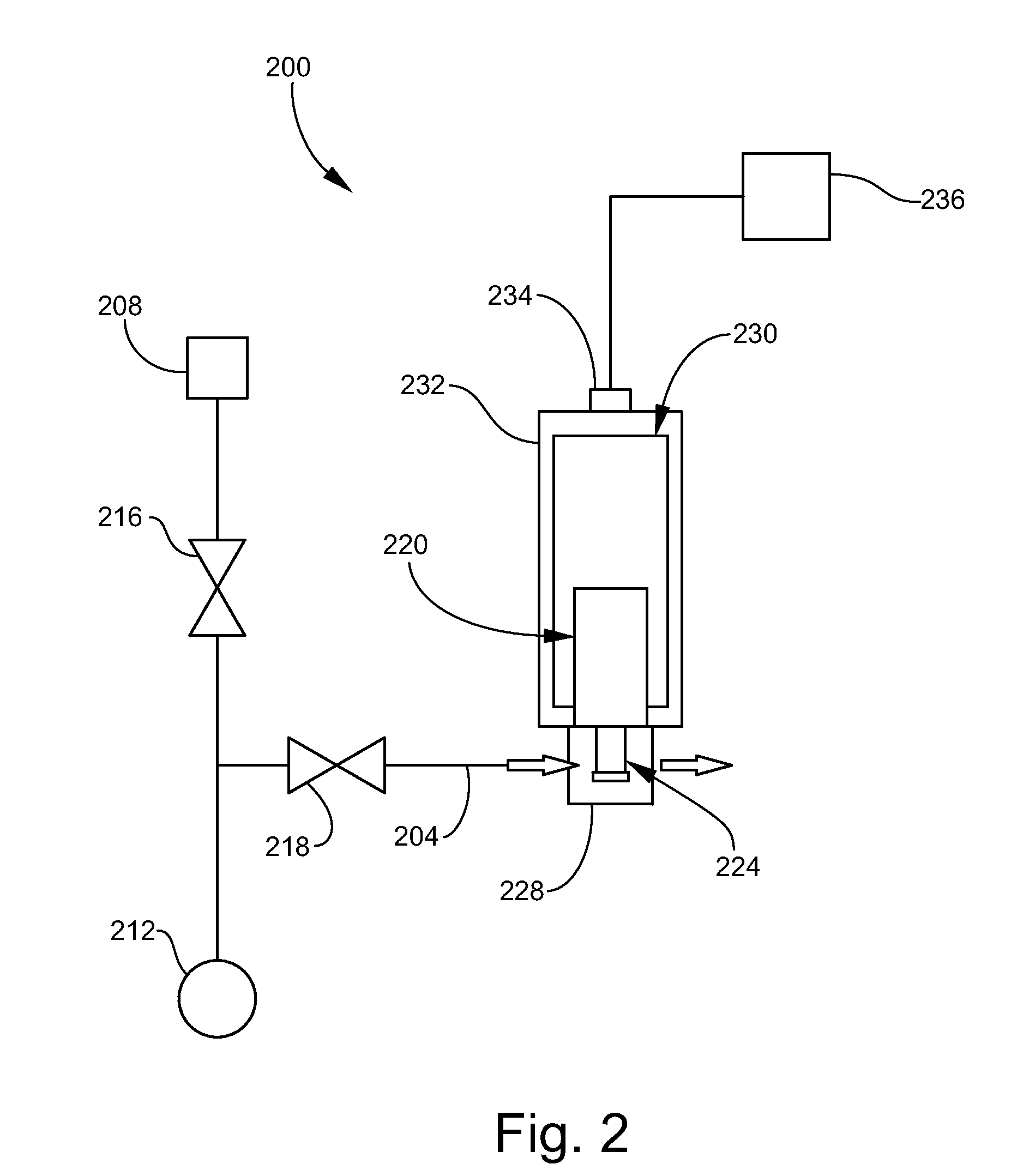
[0026]FIG. 2 is a schematic elevation view of an example of a trace gas sensing apparatus 200 according to one implementation disclosed herein. Generally, the trace gas sensing apparatus 200 may be or form a part of any of several types of leak detectors utilized in industry such as, for example, those based on accumulation leak testing, sniffing leak testing, or vacuum leak testing. The apparatus 200 may include a gas inlet line 204 communicating with a test component 208 (or with a sniffer probe), a vacuum pump 212, and one or more valves 216, 218 and other gas flow controllers (not shown) as needed for flowing tracer gas from the test component 208 to the apparatus 200. As appreciated by persons skilled in the art, the test component 208 may be directly co...


PUM

PropertyMeasurementUnit
voltage potentialaaaaaaaaaa
temperatureaaaaaaaaaa

Abstract

A trace gas sensing apparatus includes a cathode, an anode, a vacuum enclosure, and a membrane. The anode coaxially surrounds the cathode, wherein the cathode and the anode define an annular ionization chamber. The vacuum enclosure surrounds the cathode and the anode and includes a gas inlet fluidly communicating with the ionization chamber. The membrane is coupled to the gas inlet in a sealed manner and is permselective to trace gas. The apparatus may further include circuitry for applying a negative voltage potential to the cathode and for measuring an ion current signal generated by the cathode, and a magnet assembly for generating a magnetic field in the ionization chamber. The cathode may include an elongated member located along a longitudinal axis, and first and second end plates orthogonal to the longitudinal axis.

Description

FIELD OF THE INVENTION[0001]The present invention relates generally to detection of trace gas. More particularly, the invention relates to trace gas sensing apparatus and related components and methods for detection of trace gas.BACKGROUND OF THE INVENTION[0002]Trace gas leak detectors are utilized to test for leaks in various sealed components. Known leak detection systems have typically utilized a mass spectrometer to separate helium from other gas species and measure the signal. Mass spectrometers are complex and require costly components, including costly vacuum pumping systems, to sustain operation. More recently, Penning cell sensors have been employed for leak detection in response to a demand in industry for lower cost products. Systems such as described in U.S. Pat. Nos. 5,325,708; 5,661,229 and 7,266,991 utilize a Penning cell sensor to measure trace gas ion current and scale the ion current to leak rate. U.S. Pat. No. 7,497,110 describes a leak detection system utilizing ...

Claims


Application Information

Patent Timeline
Patent Type & Authority Applications(United States)
IPC IPC(8): G01N27/40G01N27/30G01N27/62
CPCG01N27/62
Inventor WALL, DAVIDGEIST, J. DANIELELLIOT, STEPHEN M.
Owner AGILENT TECH INC
Learn More