
Variable resonator, tunable filter, and electric circuit device

a variable resonator and filter technology, applied in the direction of oscillator, waveguide, resonator, etc., can solve the problems of inability to change the width of the center frequency, the effect of reducing the loss of a signal in the passband

Active Publication Date: 2012-04-26
NTT DOCOMO INC
View PDF2 Cites 2 Cited by
  • Summary
  • Abstract
  • Description
  • Claims
  • Application Information

AI Technical Summary

Benefits of technology

Enables flexible frequency tuning and significant bandwidth adjustment without increasing device size, minimizing signal loss and insertion loss, and allowing operation on various frequencies.

Problems solved by technology

Further, it is impossible to operate the filter on frequency characteristics other than previously designed frequency characteristics that each filter has.
Although the tunable filter disclosed in the Patent literature 1 has a bandwidth as a ladder type filter, the changing width of the center frequency is as small as about 1% to 2% due to the limitation of the characteristics of the piezoelectric bodies.
For this reason, variation of bandwidth is also about the same level, and a significant change of bandwidth is not possible.

Method used


Image

  • Variable resonator, tunable filter, and electric circuit device
  • Variable resonator, tunable filter, and electric circuit device
  • Variable resonator, tunable filter, and electric circuit device

Examples


Embodiment Construction

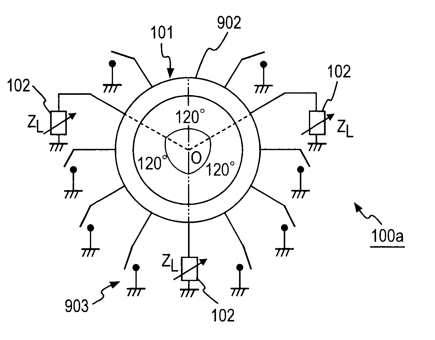
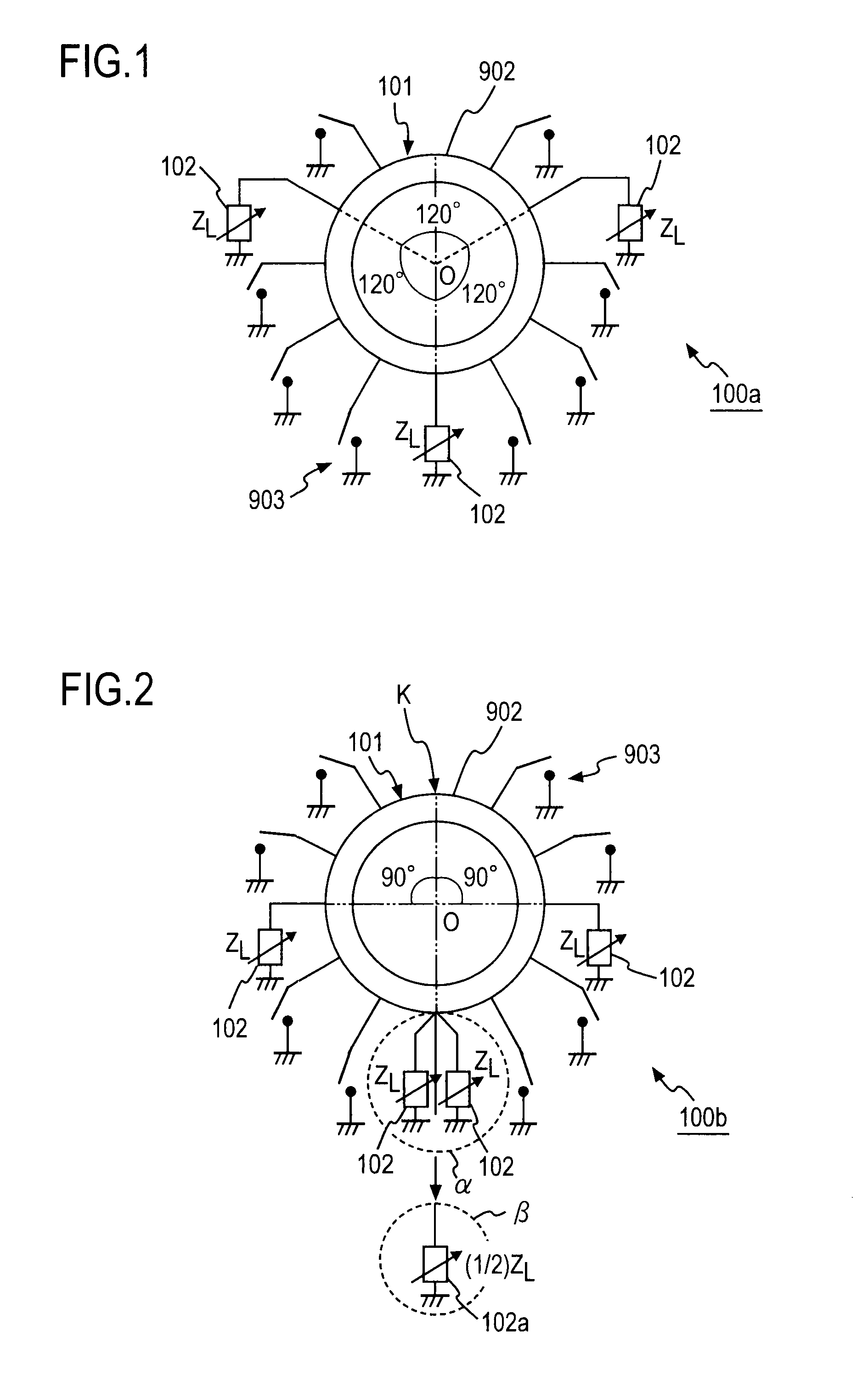
[0101]FIG. 1 shows the variable resonator 100a being one embodiment of the present invention in the case where the resonator is constituted as a microstrip line structure. The variable resonator 100a comprises a loop line body 101 being a closed circuit and N variable reactance blocks 102 (N is an integer satisfying N≧3). FIG. 1 exemplifies the variable resonator 100a in the case of N=3. As the loop line body 101, a variable resonator 900 disclosed in Japanese Patent Application No. 2006-244707 (flied and undisclosed) may be employed. So, the outline of the variable resonator 900 will be described first, and description will be made next for the variable reactance blocks 102.

[Loop Line Body]

[0102]As two specific modes of the variable resonator 900, a variable resonator 900a and a variable resonator 900b are exemplified respectively in FIG. 47A and FIG. 47B. Hereinafter, when both the variable resonator 900a and the variable resonator 900b are acceptable, reference numeral 900 is all...


PUM


Abstract

A variable resonator that comprises a loop line (902) to which two or more switches (903) are connected and N variable reactance means (102) (N≧3), in which switches (903) are severally connected to different positions on the loop line (902), the other ends of the switches are severally connected to a ground conductor, and the switches are capable of switching electrical connection / non-connection between the ground conductor and the loop line (902), the variable reactance blocks (102) are severally settable to the same reactance value, and the variable reactance blocks (102) are electrically connected to the loop line (902) as branching circuits along the circumference direction of the loop line (902) at equal electrical length intervals.

Description

CROSS-REFERENCE TO RELATED APPLICATIONS[0001]This application is a divisional application of U.S. application Ser. No. 12 / 035,035, filed Feb. 21, 2008, now allowed, the entire contents of which is incorporated herein by reference. U.S. application Ser. No. 12 / 035,035 claims the benefit of priority under 35 U.S.C. §119 from Japanese Application No. 2007-042753 filed Feb. 22, 2007.BACKGROUND OF THE INVENTION[0002]1. Field of the Invention[0003]The present invention relates to a variable resonator, a tunable filter, and an electric circuit device using the same.[0004]2. Description of the Related Art[0005]In the field of high frequency radio communication, necessary signals and unnecessary signals are separated by taking out a signal of particular frequency from a large number of signals. A circuit serving the function is called a filter, and is mounted on many radio communication devices.[0006]In a general filter, center frequency, bandwidth or the like representing the characteristic...

Claims


Application Information

Patent Timeline
Patent Type & Authority Applications(United States)
IPC IPC(8): H01P7/00H01P1/10
CPCH01P1/20381H01P7/088H01P1/2039H03B5/18
Inventor KAWAI, KUNIHIROOKAZAKI, HIROSHINARAHASHI, SHOICHI
Owner NTT DOCOMO INC
Learn More