
Valve for water faucet and method for manufacturing the same

a valve and water faucet technology, applied in the field of valves for water faucets, can solve the problems of reducing the life span of the valve for the water faucet, and achieve the effect of improving the sealing performance of the faucet and the valve life span

Inactive Publication Date: 2012-04-26
DAHATA
View PDF4 Cites 1 Cited by
  • Summary
  • Abstract
  • Description
  • Claims
  • Application Information

AI Technical Summary

Benefits of technology

[0010]The valve seat for water faucet according to one embodiment of the present invention at least has the following advantages relative to the prior art: engagement of the positioning post and the positioning hole can prevent the copper pipe sleeve from disengage from the water inlet pipe along the length direction thereof. Engagement of the positioning protrusion and the positioning notch can prevent the copper pipe sleeve from rotating relative to the copper pipe sleeve. The leak-proof rings on an outer surface of the outlet pipe seat can remarkably improve the life span of the valve for water faucet.
[0011]Another object of the present invention is to provide a method for manufacturing a valve for water faucet, which can improve the sealing performance of the faucet.
[0016]Yet another object of the present invention is to provide an outlet pipe seat with desirable sealing performance.

Problems solved by technology

However, the conventional valve for water faucet in the prior art at least has the following disadvantage.
The cold water inlet pipe defining external thread and the hot water inlet pipe defining external thread may disengage or malfunction in use, which will inevitably reduce the life span of the valve for water faucet.

Method used


Image

  • Valve for water faucet and method for manufacturing the same
  • Valve for water faucet and method for manufacturing the same
  • Valve for water faucet and method for manufacturing the same

Examples


first embodiment

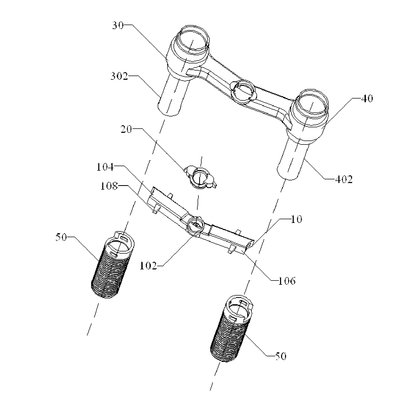
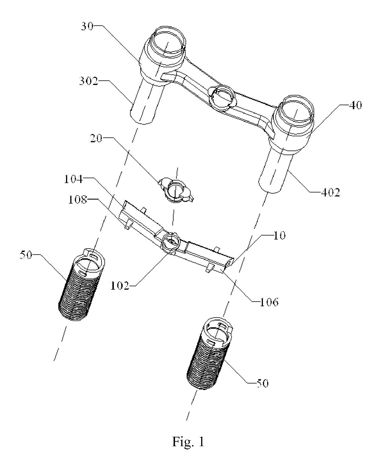
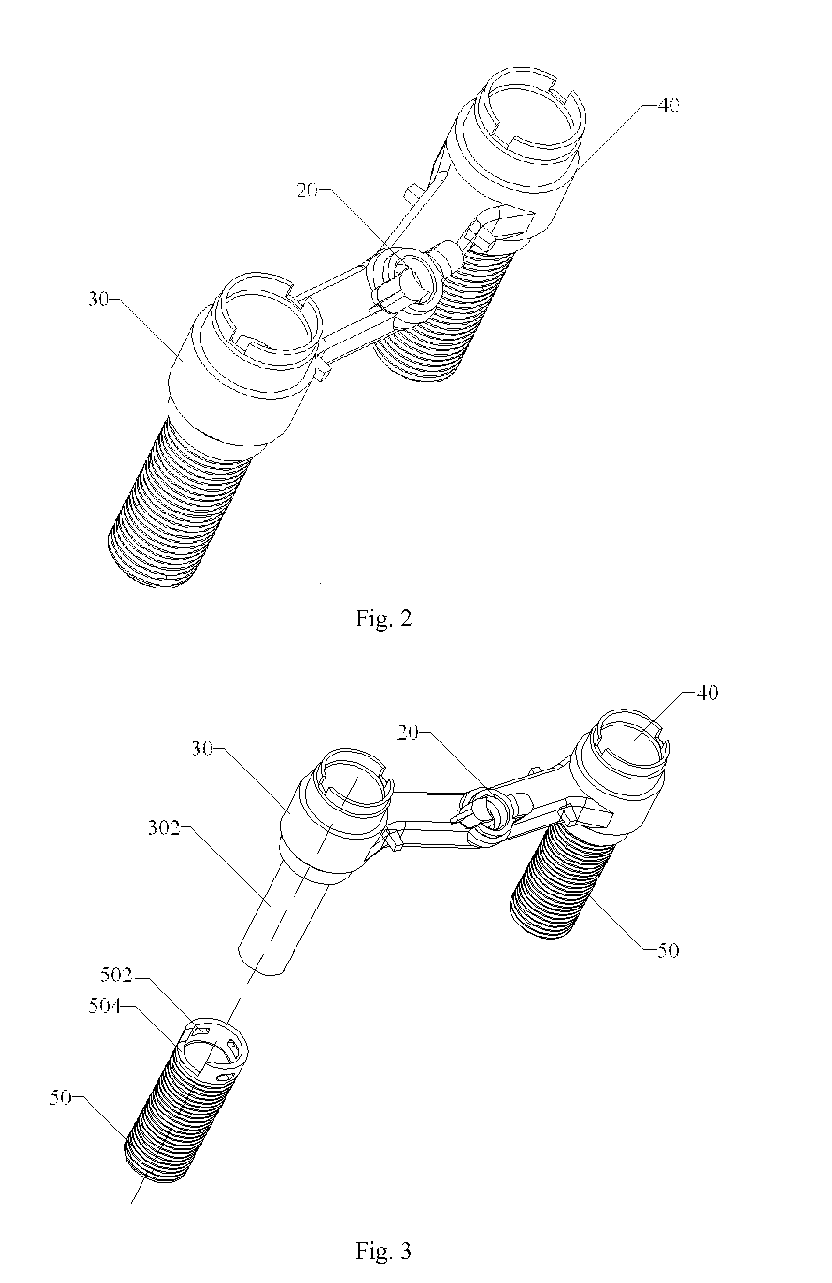
[0029]Referring to FIG. 1 to FIG. 6, according to the present invention, a valve for water faucet includes an outlet pipe seat 10, an outlet pipe connector 20 coupled to the outlet pipe seat 10, a hot water valve seat 30 and a cold water valve seat 40 integrally wrapped around the outlet pipe seat 10 and the outlet pipe connector 20 via injection molding, and a pair of copper pipe sleeves 50 defining external threads respectively secured to the hot water valve seat 30 and the cold water valve seat 40.

[0030]Referring to FIG. 1, the outlet pipe seat 10 includes a connecting seat 102 at a center thereof and a hot water pipe 104 and a cold water pipe 106 at two sides of the connecting seat 102. The outlet pipe connector 20 is hermetically seated in the connecting seat 102 and has desirable sealing performance after injection molding. Outer peripheral wall of the hot water pipe 104 and the cold water pipe 106 is provided with a number of positioning blocks 108. The positioning blocks 108...

second embodiment

[0041]FIG. 7 depicts another perspective view of an outlet pipe seat 10 of a valve for water faucet according to the present invention.

[0042]In the illustrated embodiment, the hot water pipe 104 and the cold water pipe 106 of the outlet pipe seat 10 each forms a number of annular leak-proof rings 110 which extend out from an outer surface thereof. The leak-proof rings 110 are spaced apart from each other along length direction of the hot water pipe 104 and the cold water pipe 106. In the second injection molding procedure, at least part of the leak-proof ring 110 melts, so as to improve the sealing performance of the valve for water faucet and prevent the valve for water faucet from leaking water.

[0043]In addition, in the second embodiment of the valve for water faucet of the present invention, the outlet pipe seat 10 is also disposed with a number of positioning blocks 108. However, the positioning blocks 108 are seated within the maximal profile of the outlet pipe seat 10. In othe...


PUM

PropertyMeasurementUnit
lengthaaaaaaaaaa
structureaaaaaaaaaa

Abstract

The present invention provides a valve for water faucet including an outlet pipe seat having a connecting seat via a first injection molding, an outlet pipe connector assembled to the connecting seat, and a hot water valve seat and a cold water valve seat integrally wrapping around the outlet pipe seat and the outlet pipe connector via a second injection molding. Each water valve seat includes a copper pipe sleeve secured to a water inlet pipe. The outlet pipe seat is formed with leak-proof rings on an outer surface thereof. Each water valve seat is formed with a water inlet pipe having a positioning post thereon and an annular wall set around the water inlet pipe. The copper pipe sleeve defines a positioning hole for receiving the positioning post when the copper pipe sleeve is positioned in the chamber between the annular wall and the water inlet pipe.

Description

CROSS-REFERENCE TO RELATED APPLICATION[0001]The present patent application claims the benefit of Chinese Patent Application No. 201020573302.5, filed Oct. 22, 2010, the disclosure of which is hereby incorporated herein by reference in its entirety.FIELD OF THE INVENTION[0002]The present invention generally relates to water faucets and, more specifically, relates to a valve for water faucet and method for manufacturing the same.BACKGROUND OF THE INVENTION[0003]At present, conventional valves for water faucets in the prior art generally includes an outlet pipe seat, an outlet pipe connector and a hot water valve seat and a cold water valve seat manufactured via injection molding procedure. The hot water valve seat is provided with a hot water inlet pipe defining an external thread. The cold water valve seat is provided with a cold water inlet pipe defining an external thread.[0004]However, the conventional valve for water faucet in the prior art at least has the following disadvantage...

Claims


Application Information

Patent Timeline
Patent Type & Authority Applications(United States)
IPC IPC(8): E03C1/02F16L37/00B21K1/20
CPCF16K19/006Y10T29/49412E03C1/0403E03C1/04Y10T137/6014Y10T137/87579Y10T137/9029Y10T137/9464
Inventor TZENG, JEFFERY
Owner DAHATA
Learn More