
Methods and apparatuses for electrochemical cell monitoring and control

a technology of electrochemical cells and circuits, applied in secondary cells, cell components, instruments, etc., can solve the problems of extreme temperature, damage to electrochemical cells, undesirable and unsafe reactions, etc., and achieve the effect of improving the overall safety and reliability of electrochemical cells

Active Publication Date: 2012-04-19
NORTHROP GRUMMAN SYST CORP
View PDF4 Cites 46 Cited by
  • Summary
  • Abstract
  • Description
  • Claims
  • Application Information

AI Technical Summary

Benefits of technology

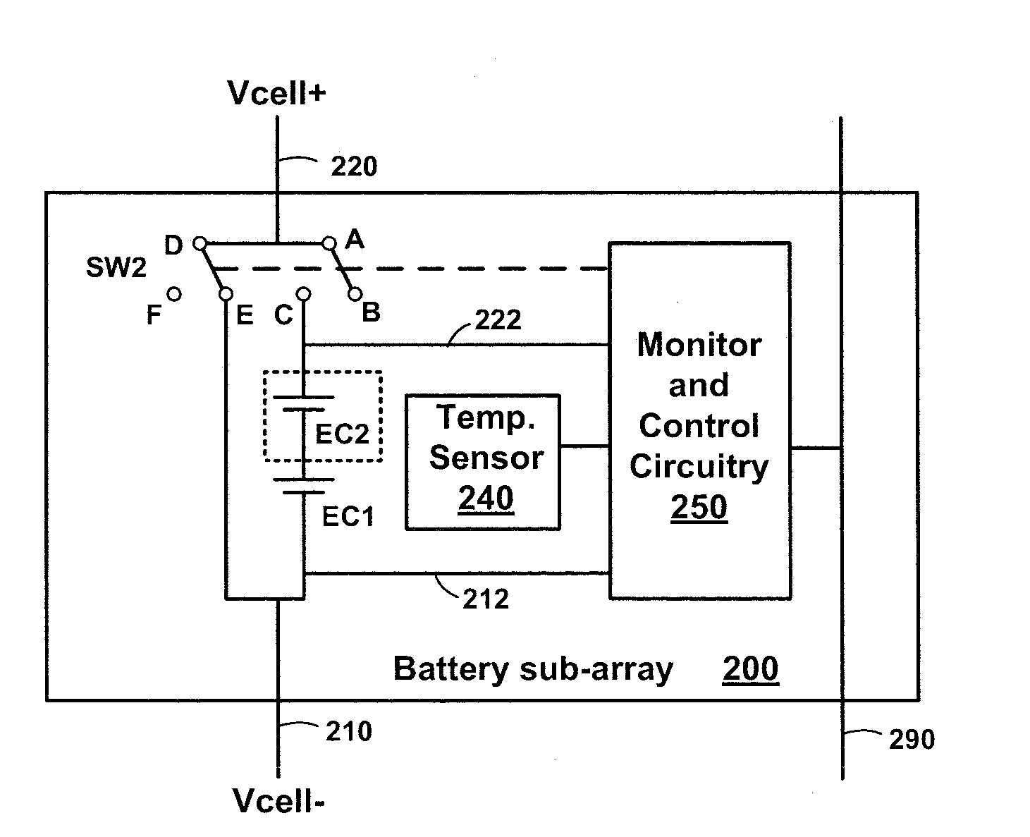
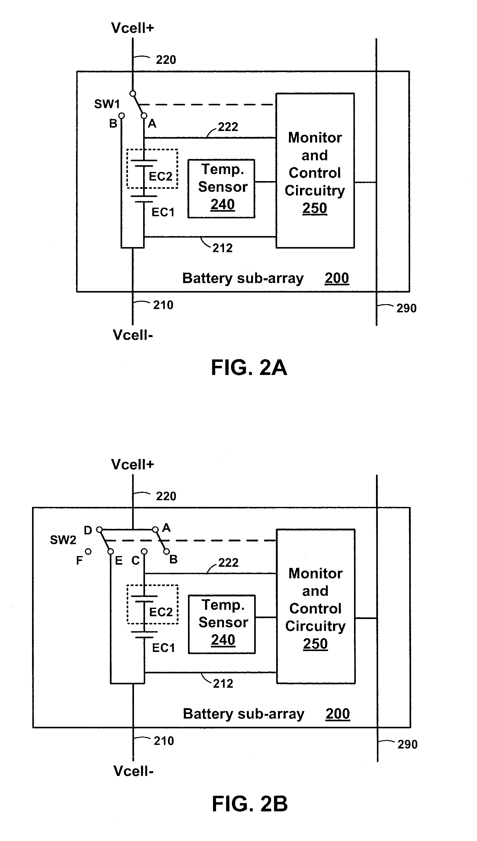
[0008]Embodiments of the present invention comprise apparatuses and methods to improve the overall safety and reliability of electrochemical cells arrayed together by monitoring and controlling the electrochemical cells at a cell level, a sub-array level, or a combination thereof.

Problems solved by technology

Electrochemical cells, particularly Li-Ion cells, can be damaged by excessive charge voltage or when discharged to too low of a voltage.
Electrochemical cells can also be damaged by extremes in temperature on both the hot extreme and the cold extreme.
Moreover, undesirable and unsafe reactions, such as cell venting, electrolyte leakage, smoke, fire, and cell rupture may occur without proper controls on environmental conditions, charging conditions, and discharging conditions.
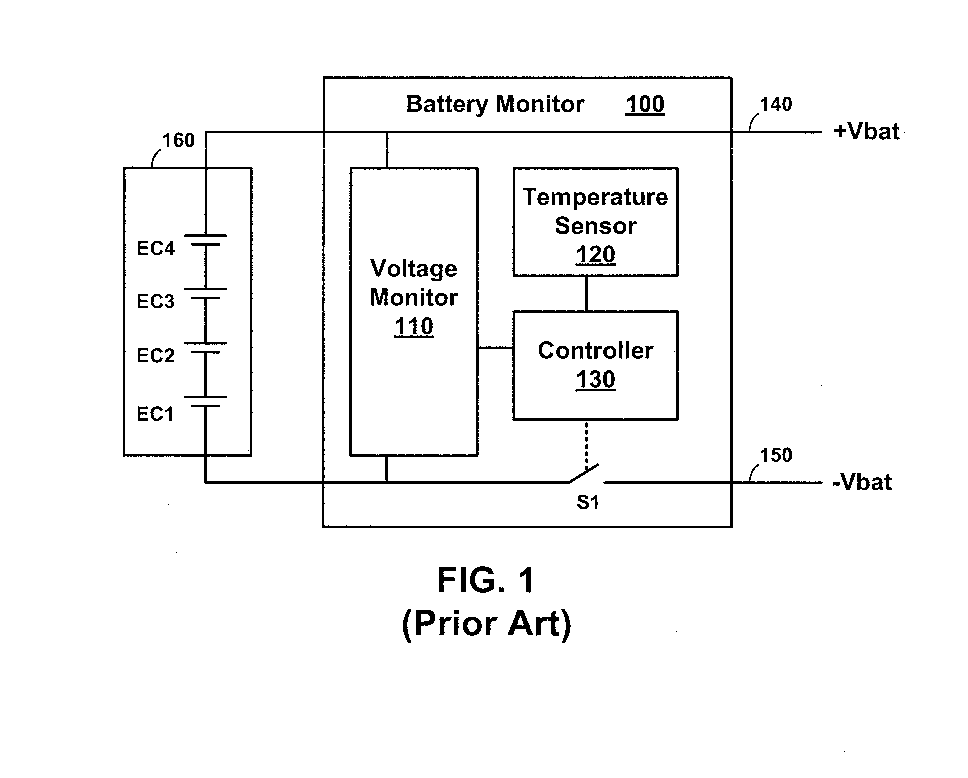
However, these proposals generally monitor the condition of the overall multi-cell battery and disconnect the multi-cell battery if an adverse condition is detected.
However, this conventional monitor and control circuit only operates on the multi-cell battery as a whole and doesn't give information or control at the individual electrochemical cell level.

Method used


Image

  • Methods and apparatuses for electrochemical cell monitoring and control
  • Methods and apparatuses for electrochemical cell monitoring and control
  • Methods and apparatuses for electrochemical cell monitoring and control

Examples


Embodiment Construction

[0026]In the following detailed description, reference is made to the accompanying drawings which form a part hereof, and in which is shown by way of illustration specific embodiments in which the invention may be practiced. These embodiments are described in sufficient detail to enable those of ordinary skill in the art to practice the invention. It should be understood, however, that the detailed description and the specific examples, while indicating examples of embodiments of the invention, are given by way of illustration only and not by way of limitation. From this disclosure, various substitutions, modifications, additions rearrangements, or combinations thereof within the scope of the present invention may be made and will become apparent to those of ordinary skill in the art.

[0027]In accordance with common practice the various features illustrated in the drawings may not be drawn to scale. The illustrations presented herein are not meant to be actual views of any particular...


PUM


Abstract

Battery sub-arrays are configured for electrical and mechanical coupling with each other to form a multi-cell battery. A sub-array may be an individual cell or a group of cells. Each sub-array includes a bypass switch to connect the sub-array within the multi-cell battery or bypass the sub-array. Monitoring and control circuitry controls the bypass switch in response to voltage measurements, temperature measurements or a combination thereof for the sub-array. Each sub-array is contained in a holder including a housing and a thermal container encompassing a substantial portion of the housing. The housing includes a cell cavity, a sensor cavity, and a circuit cavity. Positive terminals and negative terminals are positioned on sides of the holder such that when holders are mechanically abutted in an array, various electrical connections can be made to connect the cells in series, parallel, or a combination thereof.

Description

TECHNICAL FIELD[0001]Embodiments of the present invention relate generally to battery protection circuits and, more particularly, to circuits and methods for monitoring and controlling electrochemical cells.BACKGROUND[0002]Demand for batteries has been increasing dramatically. With this increase, there is a need for high-energy batteries that use multiple electrochemical cells coupled together to provide higher current and high voltage outputs.[0003]A multi-cell battery pack usually includes individual electrochemical cells connected in series to create a battery with a higher voltage. For example, four Lithium Ion (Li-Ion) electrochemical cells with a nominal voltage of about 3.6 volts may be connected in series to develop a multi-cell battery with a nominal voltage of about 14.4 volts. Two of these three-cell series-connected groupings may be connected in parallel to create a multi-cell battery including a total of six cells with twice the current capability at about 14.4 volts.[0...

Claims


Application Information

Patent Timeline
IPC IPC(8): H01M10/42H01M2/10H01M50/204H01M50/296H01M50/505H01M50/509H01M50/51H01M50/512
CPCG01R19/16542G01R31/3658H01M2/1016H01M2/202H02J7/0091H01M10/425H01M10/482H01M10/486H01M10/5004H01M6/42H01M10/613G01R31/396Y02E60/10H02J7/007194H01M50/204H01M50/509H01M50/512H01M50/51H01M50/296H01M50/505
Inventor TROUTMAN, JOSEPH M.
Owner NORTHROP GRUMMAN SYST CORP
Learn More