
Method For Producing A Hole

a technology of laser pulses and holes, applied in the direction of metal-working equipment, welding equipment, manufacturing tools, etc., can solve the problems of high cost and time-consuming of such ultra-short laser pulses, and achieve the effect of optimizing properties

Inactive Publication Date: 2012-04-19
CHROMALLOY GAS TURBINE +1
View PDF4 Cites 3 Cited by
  • Summary
  • Abstract
  • Description
  • Claims
  • Application Information

AI Technical Summary

Benefits of technology

The invention is a method and device for improving the ablation process in a hole. The method involves using different pulse lengths, particularly longer pulses for the outer surface region of the interface and shorter pulses for the interior of the hole. This approach creates optimal properties in the outer surface region and allows for longer pulses to be used in the interior without causing inhomogeneous interfaces. The method also includes using a device that allows for the combination of different measures to achieve the desired results. Overall, the invention improves the quality and efficiency of the ablation process.

Problems solved by technology

The use of such ultrashort laser pulses is expensive and very time-intensive owing to their low average powers.

Method used


Image

  • Method For Producing A Hole
  • Method For Producing A Hole
  • Method For Producing A Hole

Examples


Embodiment Construction

[0027]Description of the Component with a Hole

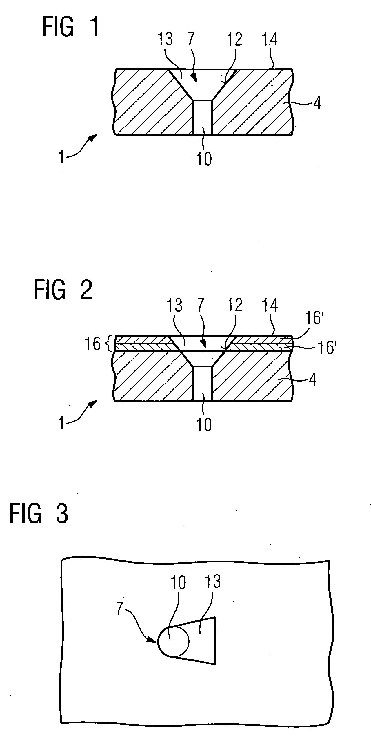
[0028]FIG. 1 shows a component 1 with a hole 7.[0029]The component 1 consists of a substrate 4 (for example a casting or DS or SX component).

[0030]The substrate 4 may be metallic and / or ceramic. Particularly in the case of turbine components, for example turbine rotor blades 120 or guide vanes 130 (FIGS. 16, 17), heat shield elements 155 (FIG. 18) and other housing parts of a steam or gas turbine 100 (FIG. 16), but also an aircraft turbine, the substrate 4 consists of a nickel-, cobalt- or iron-based superalloy. In the case of turbine blades for aircraft, the substrate 4 consists for example of titanium or a titanium based alloy.

[0031]The substrate 4 comprises a hole 7, which is for example a through-hole. It may however also be a blind hole. The hole 7 consists of a lower region 10 which starts from an inner side of the component 1 and is for example designed symmetrically (for example circularly, ovally or rectangularly), and an upper ...


PUM

PropertyMeasurementUnit
wavelengthaaaaaaaaaa
wavelengthsaaaaaaaaaa

Abstract

There is described a method for producing a hole using e.g. a lasers, wherein short laser pulse durations are used. The laser pulse durations are varied, short laser pulse durations being utilized only in the area to be removed in which an influence on the penetration behavior and discharge behavior is noticeable while longer pulse durations of >0.4 ms are used. This is the case for the inner surface of a diffuser of a hole, for example, which can be produced very accurately by means of short laser pulse durations.

Description

CROSS REFERENCE TO RELATED APPLICATIONS[0001]This application is the US National Stage of International Application No. PCT / EP2007 / 050101, filed Jan. 5, 2007 and claims the benefit thereof. The International Application claims the benefits of European Patent Office application No. 06001467.7 filed Jan. 24, 2006, both of the applications are incorporated by reference herein in their entirety.FIELD OF INVENTION[0002]The invention relates to a method for producing a hole.BACKGROUND OF INVENTION[0003]For many components, castings in particular, ablations subsequently need to be carried out for instance to form indentations or through-holes. Particularly for turbine components which have film cooling holes for cooling, holes are subsequently introduced after production of the component.[0004]Such turbine components often also have layers, for example a metallic layer or interlayer and / or a ceramic outer layer. The film cooling holes must then be produced through the layers and the substr...

Claims


Application Information

Patent Timeline
Patent Type & Authority Applications(United States)
IPC IPC(8): B23K26/38B23K26/06B23K26/42
CPCB23K26/0639B23K26/0648B23K26/388B23K26/063B23K26/0665B23K26/0622B23K26/064B23K26/389
Inventor BECK, THOMASSETTEGAST, SILKE
Owner CHROMALLOY GAS TURBINE
Learn More