
Pressure and vacuum swing adsorption separation processes

a vacuum swing and adsorption separation technology, applied in the field of molecular sieves, can solve the problems of reprocessing energy-intensive and unrecognizable references in the references of the problem of regenerating the adsorbent molecular sieve, and achieve the effect of energy saving

Active Publication Date: 2012-04-19
WINTEK IND SYST INC
View PDF7 Cites 9 Cited by
  • Summary
  • Abstract
  • Description
  • Claims
  • Application Information

AI Technical Summary

Benefits of technology

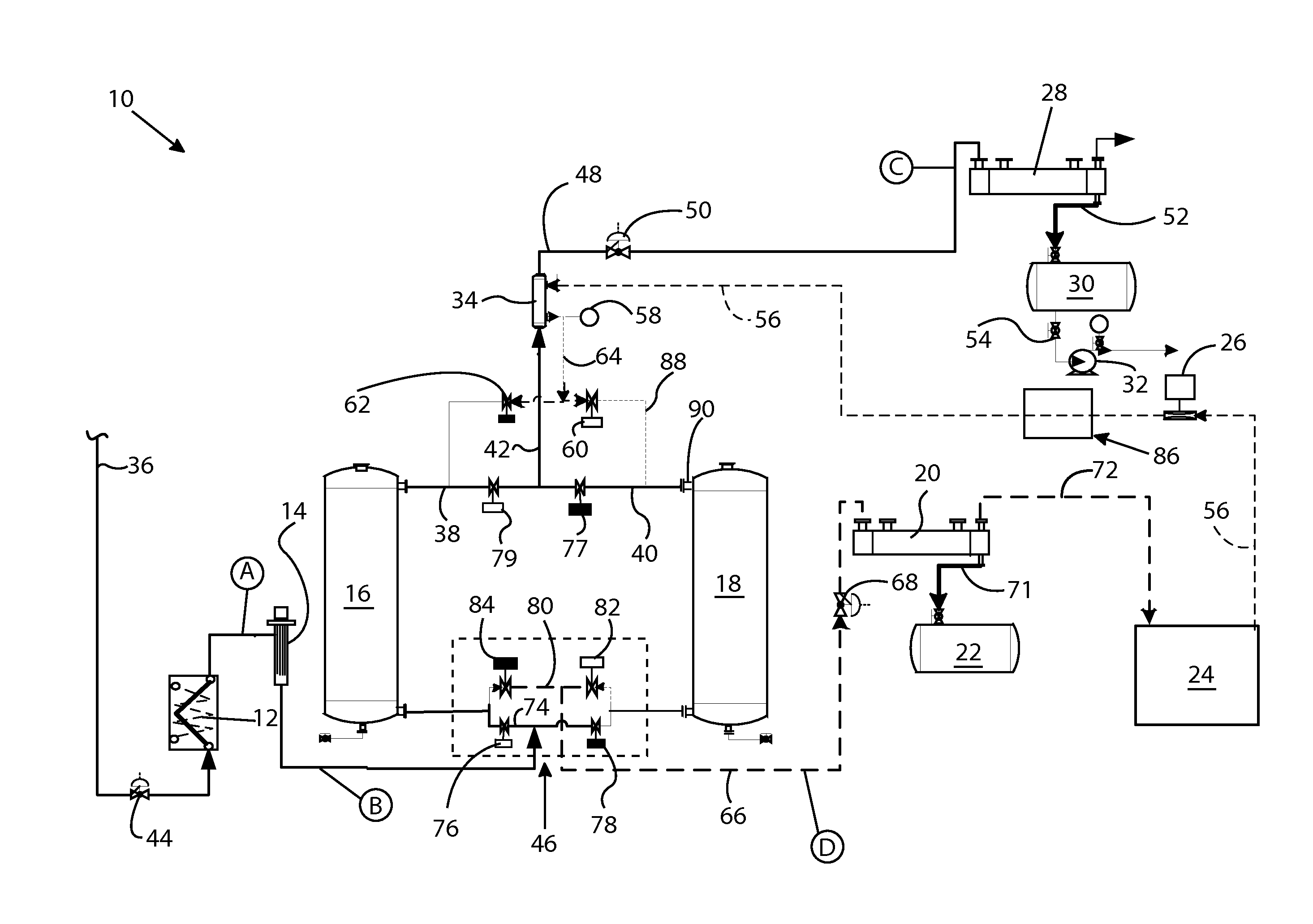
[0012]The invention heats the non-condensable gas, which is preferably nitrogen, preferably utilizing a heat exchanger operating either at atmospheric pressure or at a vacuum, preferably using the hot, dry alcohol vapor or other de-watered liquid or vapor feedstock exiting from the molecular sieves. The hot, dry alcohol vapor or other de-watered feedstock is preferably used as the heat source in the heat exchanger, to heat the non-condensable gas, which preferably is nitrogen, for energy savings. The heated non-condensable preferable nitrogen gas is preferably then expanded to perform the regeneration. The preferable nitrogen gas is preferably supplied at low absolute pressures as the purge gas to be furnished to the molecular sieves. The preferable nitrogen purge gas passes through the molecular sieves during the regeneration cycle, extracting water from the molecular sieves. Thereafter the resulting mixture of water vapor and nitrogen is preferably passed through a condenser at approximately the same pressure as the regeneration pressure in the molecular sieve, and then through a pump that cools and compresses the nitrogen to essentially atmospheric pressure. The nitrogen is then heated and expanded to low absolute pressure, thereby completing the cycle in an essentially closed loop.

Problems solved by technology

However, there does not appear to be any recognition in the references of the problem of regenerating the adsorbent molecular sieves other than the conventional approach of using a stream of purified alcohol vapor.
Such reprocessing is energy-intensive.

Method used


Image

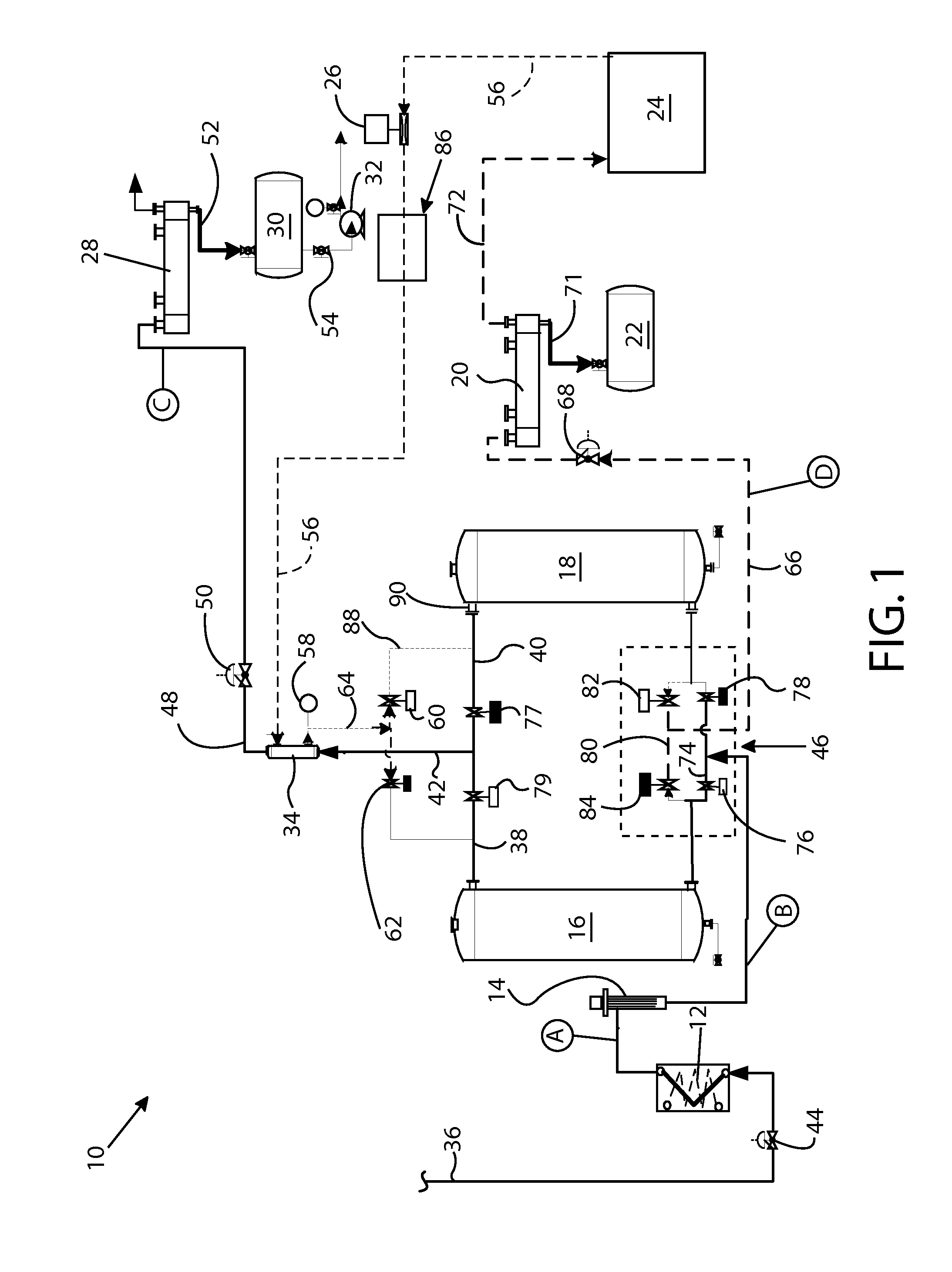
  • Pressure and vacuum swing adsorption separation processes
  • Pressure and vacuum swing adsorption separation processes
  • Pressure and vacuum swing adsorption separation processes

Examples


##ic example 1

Prophetic Example 1

[0079]A feedstock of 3870 pounds per hour of isopropyl alcohol with 120 pounds of water per hour will be introduced via line 36. At location A, the feedstock is expected to be all vapor at 63 psia and 255° F. After passing through superheater 14, the properties of the feedstock at location B are expected to be all vapor at 62 psia 305° F., which is a flow rate of 148 Actual Cubic Feet per Minute (ACFM). This feedstock will then be fed alternatingly through first and second primary molecular sieve units 16, 18 with the duration of feedstock passage through the operative one of molecular sieve units 16, 18 being 5 minutes. The feedstock exiting the operative one of first and second primary molecular sieve units 16, 18, after passing through gas-to-gas heat exchanger 34 and arriving at location C is expected to exhibit the following properties: 15 psia, 175° F. with approx 80% still vapor, but devoid of water. It is expected that after passing through condenser 28 an...

##ic example 2

Prophetic Example 2

[0082]A feedstock of 3826 pounds per hour of ethanol with 161 pounds per hour of water will be introduced via line 36. At location A, the feedstock is expected to be all vapor at 63 psia and 250° F. After passing through superheater 14, the feedstock at location B is expected to be all vapor at 62 psia, 300° F., which is a flow rate of 192 Actual Cubic Feet per Minute (ACFM). The feedstock will then be fed alternatingly through first and second primary molecular sieve units 16, 18 with the duration of feedstock passage through the operative one of molecular sieve units 16, 18 being five minutes. The feedstock exiting the operative one of first and second primary molecular sieve units 16, 18, after passing through gas-to-gas heat exchanger 34 and arriving at location C will be expected to exhibit the following properties: 15 psia, 175° F. with approx 80% remaining as vapor, but devoid of water. It is expected that after passing through condenser 28 and through unit...

##ic example 3

Prophetic Example 3

[0085]A feedstock of 3845 pounds per hour of methanol with 202 pounds per hour of water will be introduced via line 36. At location A, the feedstock is expected to be all vapor at 63 psia and 225° F. After passing through superheater 14, the feedstock at location B is expected to be all vapor at 62 psia, 275° F., which is a flow rate of 266 Actual Cubic Feet per Minute (ACFM). The feedstock will then be fed alternatingly through first and second primary molecular sieve units 16, 18 with the duration of feedstock passage through the operative one of molecular sieve units 16, 18 being five minutes. The feedstock exiting the operative one of first and second primary molecular sieve units 16, 18, after passing through gas-to-gas heat exchanger 34 and arriving at location C, is expected to be at 15 psia, 150° F., approximately 80% still vapor, but devoid of water. It is expected that after passing through condenser 28 and through unit 32, 99.5% dry methanol will result...


PUM

PropertyMeasurementUnit
Pressureaaaaaaaaaa
Flow rateaaaaaaaaaa

Abstract

A pressure or vacuum swing adsorption process for separating water from solvent utilizing molecular sieves and regenerating the molecular sieve by passing non-condensable recycled gas along the molecular sieve, capturing the recycled gas and using the recycled gas again to repeat regeneration of the molecular sieve.

Description

CROSS-REFERENCE TO RELATED PATENT APPLICATION[0001]This application claims the benefit, under 35 USC 119 and 120, of the priority of U.S. Ser. No. 61 / 392,503 for “Pressure and Vacuum Swing Adsorption Separation Processes”, filed 13 Oct. 2010 in the name of Paul M. Winter.BACKGROUND OF THE INVENTION[0002]1. Field of the Invention[0003]This invention relates to use of molecular sieves in pressure swing adsorption and vacuum swing adsorption processes for dehydrating feedstocks of alcohols and other gases or vapors, and further relates to methods and apparatus for periodically regenerating the molecular sieves for continuing successful practice of the dehydrating processes.[0004]As used herein, the term “vapor” refers to a gas that is easily condensable at normal operating temperatures and pressures, whereas the term “gas” refers to the gaseous phase material that is not readily or ordinarily condensable at conventional operating temperatures and pressures. More specifically, the term ...

Claims


Application Information

Patent Timeline
IPC IPC(8): B01D53/047
CPCB01D53/0476B01D2259/404B01D53/72B01D53/75B01D2253/116B01D2253/308B01D2256/24B01D2257/40B01D2257/7022B01D2257/7027B01D2257/704B01D2257/80B01D2259/40056B01D2259/402B01D53/261
Inventor WINTER, PAUL M.
Owner WINTEK IND SYST INC
Learn More