
Ink jet recording head and method of producing ink jet recording head

Active Publication Date: 2012-04-12
CANON KK
View PDF1 Cites 9 Cited by
  • Summary
  • Abstract
  • Description
  • Claims
  • Application Information

AI Technical Summary

Benefits of technology

[0011]In view of the foregoing, an object of the present invention is as described below. The object is to provide the following ink jet recording head and a method of producing the ink jet recording head. In the ink jet recording head, ejection orifices can be densely formed by employing a photolithography technique. The ink jet recording head suppresses a displacement between the positions on which a main droplet and a sub-droplet impinge while achieving an increase in its recording speed, and hence can realize an improvement in the quality of an image.
[0013]According to the present invention, there is provided the following ink jet recording head and a method of producing the ink jet recording head. In the ink jet recording head, ejection orifices can be densely formed by employing a photolithography technique. The ink jet recording head suppresses a displacement between the positions on which a main droplet and a sub-droplet impinge while achieving an increase in its recording speed, and hence can realize an improvement in the quality of an image.

Problems solved by technology

However, the processing by polishing may be difficult in such an ink jet recording head that an ejection orifice surface is formed of a photosensitive resin material that is an organic substance and an ejection orifice of the surface is formed by employing a photolithography technique.
As a result, it may become difficult to array nozzles densely.

Method used


Image

  • Ink jet recording head and method of producing ink jet recording head
  • Ink jet recording head and method of producing ink jet recording head
  • Ink jet recording head and method of producing ink jet recording head

Examples


examples 1 to 8

[0063]Hereinafter, an exemplary embodiment of the present invention is described in detail.

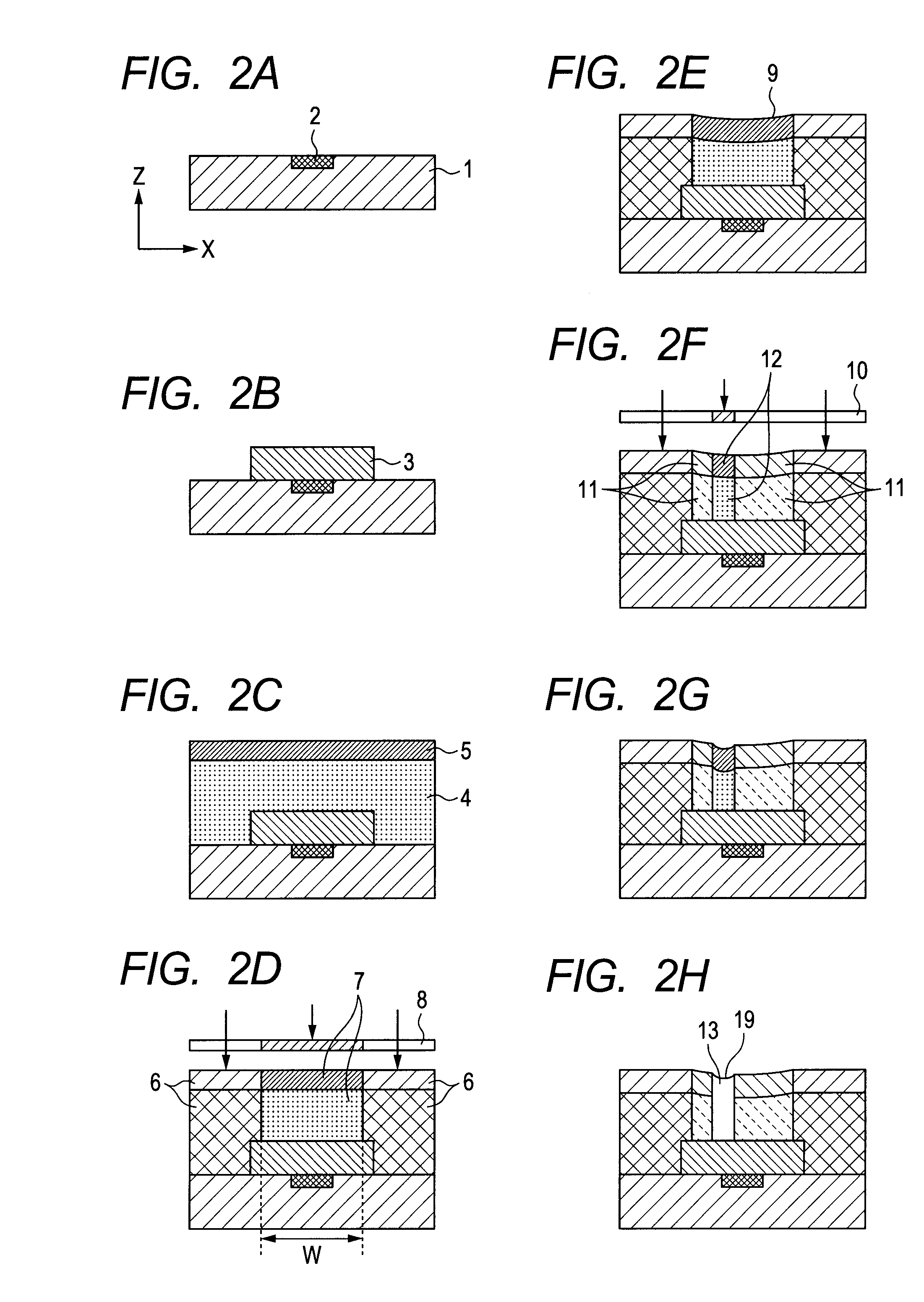
[0064]An ink jet recording head was produced by employing the steps of FIGS. 2A to 2H. As illustrated in FIG. 2A, polymethyl isopropenyl ketone as a photosensitive resin material (manufactured by TOKYO OHKA KOGYO Co., Ltd., trade name: ODUR-1010) was applied onto the substrate 1 (FIG. 2A) provided with the energy-generating element 2 so as to have a thickness of 14 μm. Next, the ink flow path-forming material layer 3 serving as a mold of an ink flow path was formed with an exposing apparatus UX3000 (trade name, Ushio Inc.) (FIG. 2B).

[0065]Next, as illustrated in FIG. 2C, a cationic polymerization type photo-curable resin material having the composition illustrated in Table 1 was applied onto the mold of an ink flow path from the surface of the substrate (surface of the substrate 1 on the side where a photosensitive resin layer was to be provided) so as to have a thickness of 25 μm, and was the...


PUM


Abstract

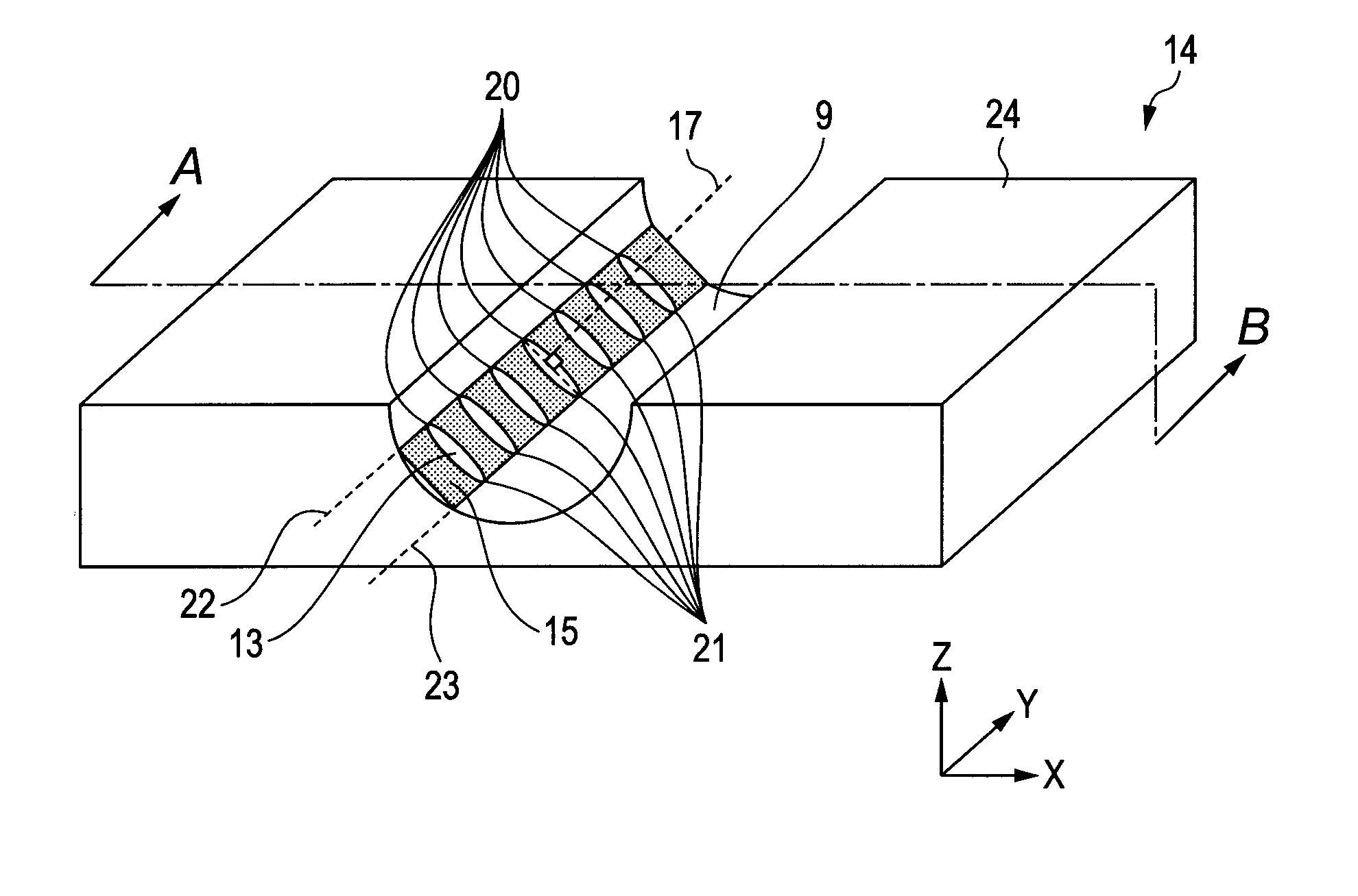
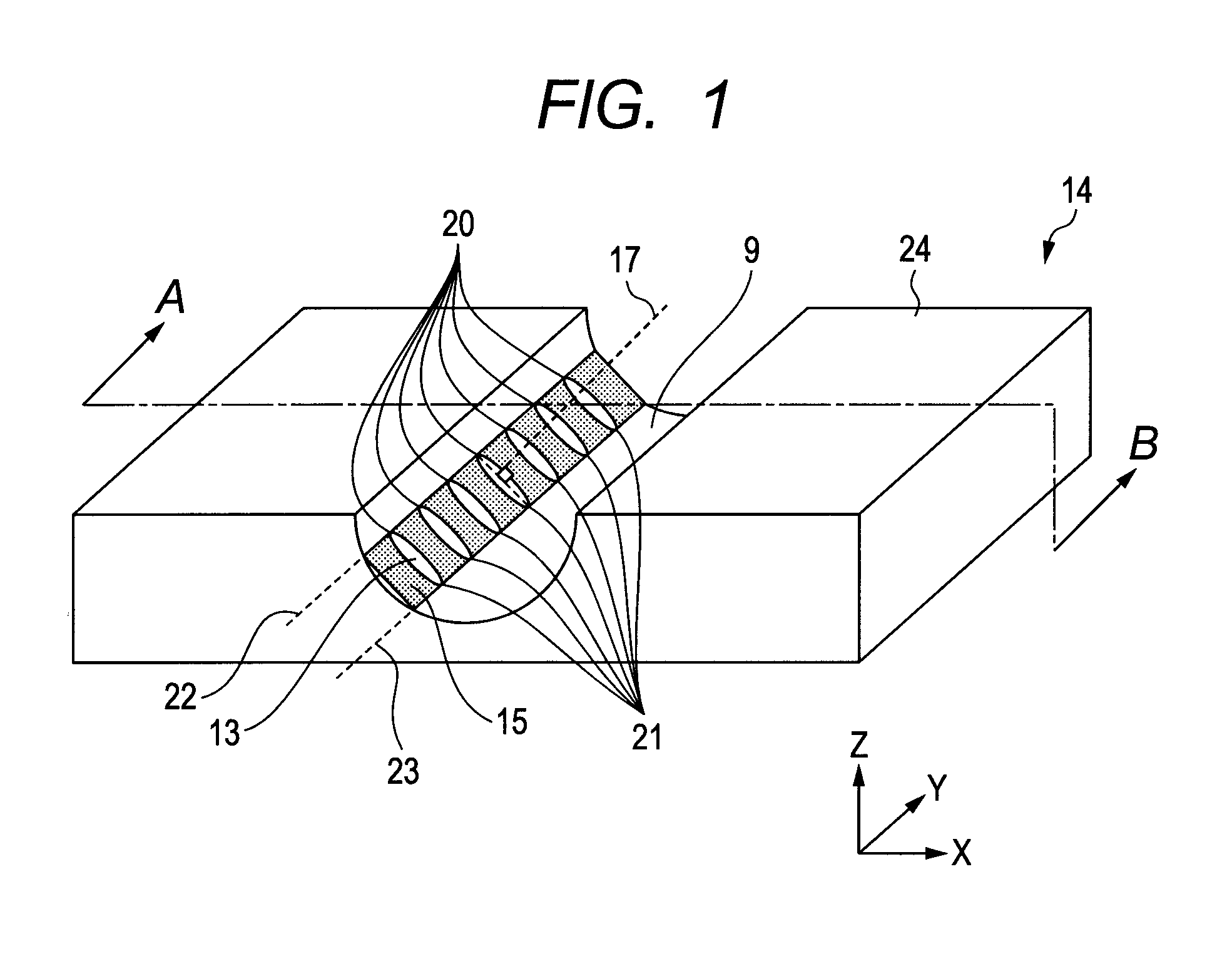
Provided is an ink jet recording head, including multiple ejection orifices for ejecting droplets to a recording medium, in which a normal of a plane formed of the following straight lines is tilted with respect to an axis line of each of the ejection orifices: a straight line obtained by connecting points, which are positioned on peripheries of the respective ejection orifices and are at shortest distances from a face plane, in a longitudinal direction of an ejection orifice array; and a straight line obtained by connecting points, which are positioned on the peripheries of the respective ejection orifices and are at longest distances from the face plane, in the longitudinal direction of the ejection orifice array.

Description

BACKGROUND OF THE INVENTION[0001]1. Field of the Invention[0002]The present invention relates to an ink jet recording head capable of ejecting a droplet of ink or the like and a method of producing an ink jet recording head.[0003]2. Description of the Related Art[0004]An ink jet recording apparatus is generally formed of an ink jet recording head provided with multiple ejection orifices and a carriage for causing the ink jet recording head to scan the top of a recording medium. In addition, the apparatus performs recording by causing nozzles to eject ink droplets while moving the ink jet recording head on the recording medium.[0005]In an ink jet recording mode, the ink droplets to be ejected from the nozzles are classified into a main droplet and a sub-droplet produced as a result of separation from the main droplet. The sub-droplet is a small ink droplet and ejected at a slow speed as compared with the main droplet. Accordingly, the sub-droplet generally impinges on a position on t...

Claims


Application Information

Patent Timeline
IPC IPC(8): B41J2/01G03F7/20
CPCB41J2/1603B41J2/1626B41J2/1631G03F7/26B41J2/1645G03F7/038G03F7/2026B41J2/1639
Inventor HAMADE, YOHEI
Owner CANON KK
Learn More