
Imprinting method

a technology of printing method and printing plate, which is applied in the direction of photomechanical equipment, manufacturing tools, instruments, etc., can solve the problems of pattern undesired deformation, increase in transfer time, and deterioration of dimensional accuracy, and achieve the effect of short tim

Inactive Publication Date: 2012-04-05
CANON KK
View PDF43 Cites 24 Cited by
  • Summary
  • Abstract
  • Description
  • Claims
  • Application Information

AI Technical Summary

Benefits of technology

The present invention provides a method for quickly filling the gap between a mask and a substrate with gas during imprinting. This can help to reduce the amount of gas near the mask, improving the quality of the imprint.

Problems solved by technology

Although the heat cycle method involves an increase in the transfer time due to temperature control and a deterioration in the dimensional accuracy due to temperature change, such problems do not exist in the photo-curing method.
In the SFIL, when a mask is brought into contact with a resin applied to a substrate, a pattern may undesirably be deformed if gas remains near the mask.
This increases pressure loss and prevents the advantageous flow of the gas.
Thus, it has been a concern that the narrow space may not necessarily be filled with a predetermined gas.
However, in this case, the processing time required for filling the gas becomes longer, resulting in a significant decrease in productivity of the overall imprinting apparatus production.

Method used


Image

  • Imprinting method
  • Imprinting method
  • Imprinting method

Examples


first embodiment

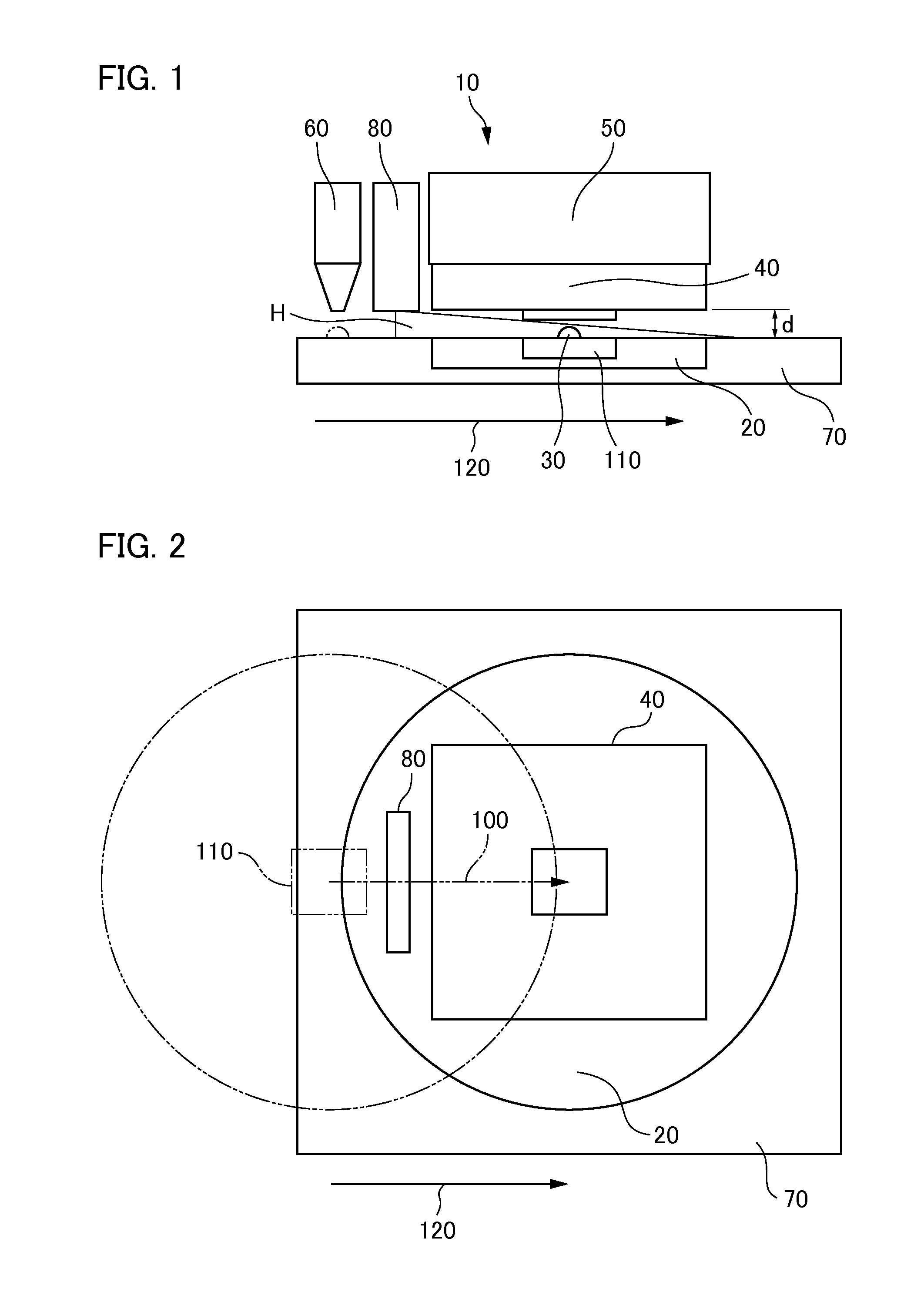
[0028]An imprinting method of a first embodiment will be described with reference to FIG. 4. It is preferable that the gas “H” to be supplied from the gas supply nozzle 80 is supplied at a high concentration to the gap “d” between the mask 40 and the substrate 20.

[0029]As described above, the flow of the gas “H” is approximated by the Couette flow between the fixed mask 40 and the substrate stage 70. Thus, the gas “H” is caused to flow into the gap “d” immediately after the gas “H” has been supplied to the shot area 110 of the substrate 20, and the concentration of the gas “H” filled in the gap “d” becomes higher when the movement distance of the shot area 110 after passing through the shot position of the shot area 110 becomes longer. Thus, in the first embodiment, the gas supply nozzle 80 is arranged at a position as near to the mask 40 as possible.

second embodiment

[0030]An imprinting method of a second embodiment will be described with reference to FIG. 5. In the second embodiment, after the shot area 110 of the substrate 20 has passed through the shot position towards the driving direction 120, the substrate stage is made so as to return the shot area 110 back to the shot position again toward a reverse direction 130. By means of such process, the motion distance of the shot area 110 after passing through the shot position becomes longer, whereby the concentration of the gas “H” in the gap “d” may be increased.

third embodiment

[0031]An imprinting method of a third embodiment will be described with reference to FIG. 6. In the third embodiment, a description will be given of a method for the case that the size of the gas supply nozzle 80 cannot be greater than that of the shot area 110 as shown in FIG. 2. When the width of the gas supply nozzle 80 is smaller than that of the shot area 110, an area in which the gas “H” is not directly supplied may be produced. Consequently, the variation in the concentration of the gas “H” immediately after being supplied may occur, and thus, it is difficult to increase the concentration of the gas “H” in the gap “d”. Thus, in the third embodiment, after the shot area 110 of the substrate 20 has moved to the shot position, the shot area 110 is moved by changing the orientation of the shot area 110 by 90 degrees with respect to the driving direction 120. By moving the shot area 110 of the substrate 20 in this way, even when the width of the gas supply nozzle 80 cannot be grea...


PUM

PropertyMeasurementUnit
distanceaaaaaaaaaa
areaaaaaaaaaaa
flow rateaaaaaaaaaa

Abstract

Provided is an imprinting method for transferring a pattern formed on a mold to a substrate, the imprinting method including applying a resin to a predetermined shot area on the substrate; moving the shot area from an application position to an imprinting position; supplying gas to the shot area; and imprinting the mold into the shot area, wherein, in the gas supply step, gas is supplied only from a gas supplying unit located above a moving path extending from the application position to the imprinting position, and the supply of the gas is started before the shot area passes beneath the gas supplying unit to thereby supply the gas to the shot area while moving it.

Description

BACKGROUND OF THE INVENTION[0001]1. Field of the Invention[0002]The present invention relates to an imprinting method for transferring a nano-scale fine pattern formed on a mask to a resin applied on a substrate.[0003]2. Description of the Related Art[0004]Imprinting technology is a technology that enables transferring a nano-scale fine pattern, and is being practically implemented as one of the nano-lithography technologies for facilitating the mass production of magnetic storage media and semiconductor devices. In imprinting technology, a mold (mask) on which a fine pattern is formed using an electron beam lithography system or the like is employed as an original plate to thereby transfer the pattern onto a substrate such as a silicon substrate, a glass plate, or the like. The pattern transfer is performed by applying a resin to a substrate, and curing the resin in a state in which the mask pattern is in contact with the resin. A heat cycle method and a photo-curing method are exa...

Claims


Application Information

Patent Timeline
Patent Type & Authority Applications(United States)
IPC IPC(8): B29C59/02
CPCG03F7/0002B82Y40/00B82Y10/00
Inventor NARIOKA, SHINTAROUEMOTO, KEIJIARAI, TSUYOSHI
Owner CANON KK
Learn More