
Fluidics system for sequential delivery of reagents

a technology of reagents and fluids, applied in the field of fluid systems for sequential delivery of reagents, can solve the problems of difficult use of miniaturized, less accessible surfaces, difficult or inefficient complete purging and removal of successive reagents, etc., and achieve the effect of convenient miniaturization

Active Publication Date: 2012-03-29
LIFE TECH CORP
View PDF7 Cites 48 Cited by
  • Summary
  • Abstract
  • Description
  • Claims
  • Application Information

AI Technical Summary

Benefits of technology

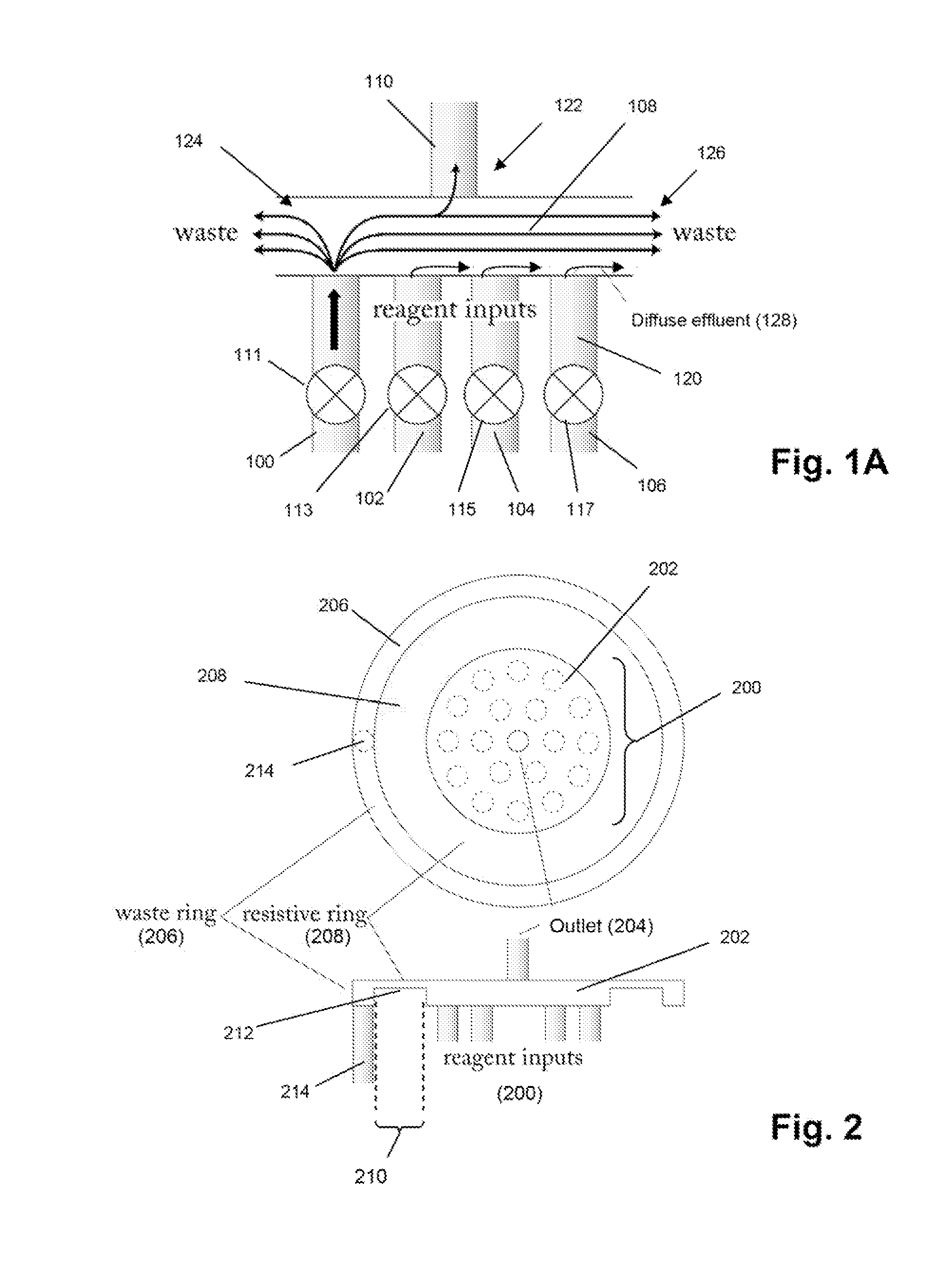
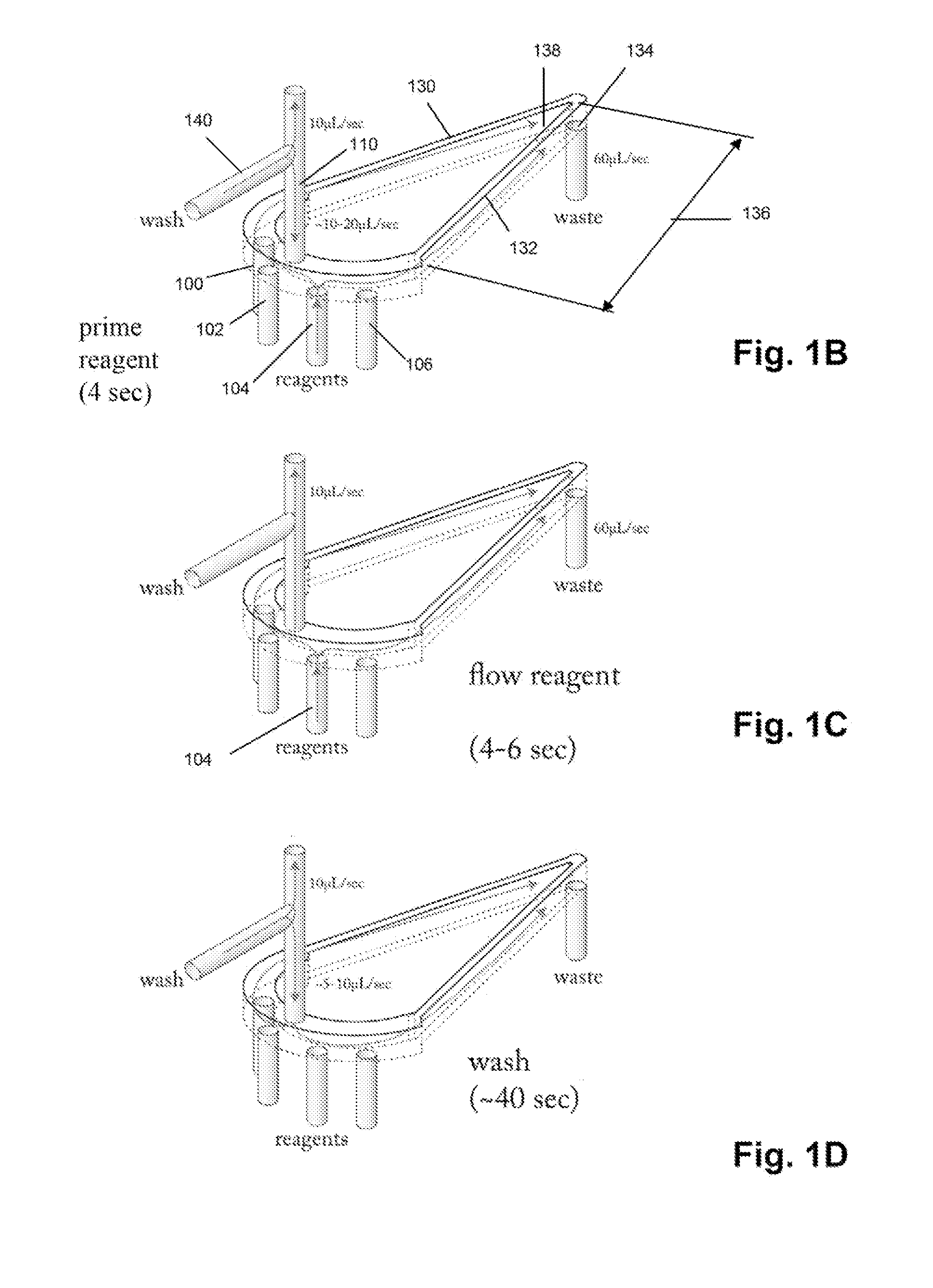
The present invention provides apparatus and methods for delivering multiple fluids to a common volume without intermixing or cross contamination. The invention includes a passive fluidics circuit that sequentially directs different fluids to a reaction chamber or flow cell using valves and differential pressures. The fluidics circuit can be miniaturized and used in processes where a stable reference potential is required. The technical effects of the invention include improved accuracy and efficiency in chemical and biological processes, as well as reduced size and cost of the apparatus.

Problems solved by technology

Although fluidics systems are available for selectively switching multiple reagent solutions to a common chamber for processing, they suffer from several deficiencies, including but not limited to, the presence of large surface areas that can adsorb or retain reagents, large physical size which makes it difficult to use with miniaturized fluidics components, e.g. see Rothberg et al (cited above), less accessible surfaces including edges and / or corners which make complete purging and removal of successive reagents difficult or inefficient, and the use of moving parts which can wear out and lead to higher manufacturing and assembly costs, e.g. Hunkapiller, U.S. Pat. No. 4,558,845; Wittmann-Liebold et al, U.S. Pat. No. 4,008;736; Farnsworth et al, U.S. Pat. No. 5,082,788; Garwood et al, U.S. Pat. No. 5,313,984; or the like.

Method used


Image

  • Fluidics system for sequential delivery of reagents
  • Fluidics system for sequential delivery of reagents
  • Fluidics system for sequential delivery of reagents

Examples


Embodiment Construction

[0016]The practice of the present invention may employ, unless otherwise indicated, conventional techniques and descriptions of mechanical engineering, electronics, fluid mechanics, and materials science, which are within the skill of the art. Such conventional techniques include, but are not limited to, design and fabrication of fluidics and microfluidics devices, and the like. Specific illustrations of suitable techniques can be had by reference to the example herein below. However, other equivalent conventional procedures can, of course, also be used.

[0017]The invention provides methods and apparatus for rapidly and cleanly switching flows of different fluids to a common outlet using a fluidics circuit. In one aspect, the fluidics circuit of the invention is combined with fluidic reservoirs, valves, pressure sources, pumps, control systems, and / or like components, to form a fluidics system for delivering separate fluid flows having predetermined rates and durations to a common vo...


PUM

PropertyMeasurementUnit
volume capacitiesaaaaaaaaaa
lengthaaaaaaaaaa

Abstract

The invention provides a passive fluidics circuit for directing different fluids to a common volume, such as a reaction chamber or flow cell, without intermixing or cross contamination. The direction and rate of flow through junctions, nodes and passages of the fluidics circuit are controlled by the states of upstream valves (e.g. opened or closed), differential fluid pressures at circuit inlets or upstream reservoirs, flow path resistances, and the like. Free diffusion or leakage of fluids from unselected inlets into the common outlet or other inlets at junctions or nodes is prevented by the flow of the selected inlet fluid, a portion of which sweeps by the inlets of unselected fluids and exits the fluidics circuit by waste ports, thereby creating a barrier against undesired intermixing with the outlet flow through leakage or diffusion. The invention is particularly advantageous in apparatus for performing sensitive multistep reactions, such as pH-based DNA sequencing reactions.

Description

[0001]This is a continuation-in-part of U.S. patent applications Ser. Nos. 12 / 474,897 and 12 / 475,311 both filed 29 May 2009, and claims priority under U.S. provisional application Ser. No. 61 / 291,627 filed 31 Dec. 2009. Both of the foregoing applications are incorporated by reference in their entireties.BACKGROUND[0002]Many applications require the regulation of multiple fluid flows in a manner that minimizes intermixing or cross-contamination of the different fluids. Such applications include multi-step synthetic or analytical processes that are carried out in a common volume and that comprise successive cycles of reagent delivery using fluids from separate reservoirs, e.g. Margulies et al. Nature, 437: 376-380 (2005); Merrifield et al, U.S. Pat. No. 3,531,258; Caruthers et al. U.S. Pat. No. 5,132,418; Rothberg et al, U.S. patent publication 2009 / 0127589; and the like. Although fluidics systems are available for selectively switching multiple reagent solutions to a common chamber f...

Claims


Application Information

Patent Timeline
Patent Type & Authority Applications(United States)
IPC IPC(8): F17D1/00B01L3/00
CPCB01J2219/00389B01L3/502715B01L3/502738B01L3/502769B01L3/502776B01L2300/0636B01L2300/0645B01L2300/0861B01L2300/0864B01L2300/0874B01L2300/0877B01L2400/0487C12Q1/6869G01N27/447G01N35/1002G01N35/1097B01J2219/00394B01L3/52B01L3/50273B01L3/502C12Q2565/629C12Q2527/119Y10T137/85938Y10T137/0318Y10T137/0424B01L3/502746B01L2200/16B01L2300/0867
Inventor SCHULTZ, JONATHANMARRAN, DAVID
Owner LIFE TECH CORP
Learn More