
Rug hold down corner

Inactive Publication Date: 2012-03-29
CRENSHAW SR EARLIE LEE
View PDF19 Cites 17 Cited by
  • Summary
  • Abstract
  • Description
  • Claims
  • Application Information

AI Technical Summary

Benefits of technology

[0013]One object of the present invention is to provide a rug hold down corner that provides a removable weight that slips upon the corner of a rug.
[0016]Another object is to provide such a rug hold down corner that has a low cost of manufacturing so the purchasing homeowners, decorators, business establishments, and organizations can readily buy the rug hold down corner through stores and supply sources.

Problems solved by technology

These methods though tend to damage the floor beneath a carpet and perform poorly when one rug is placed upon another as some people desire and some decors require.
However, the guards only attach to an exterior surface of a cover using adhesive.

Method used


Image

  • Rug hold down corner
  • Rug hold down corner
  • Rug hold down corner

Examples


Embodiment Construction

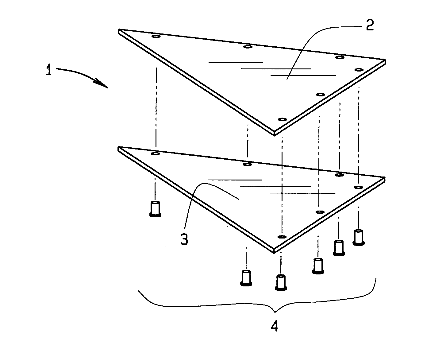
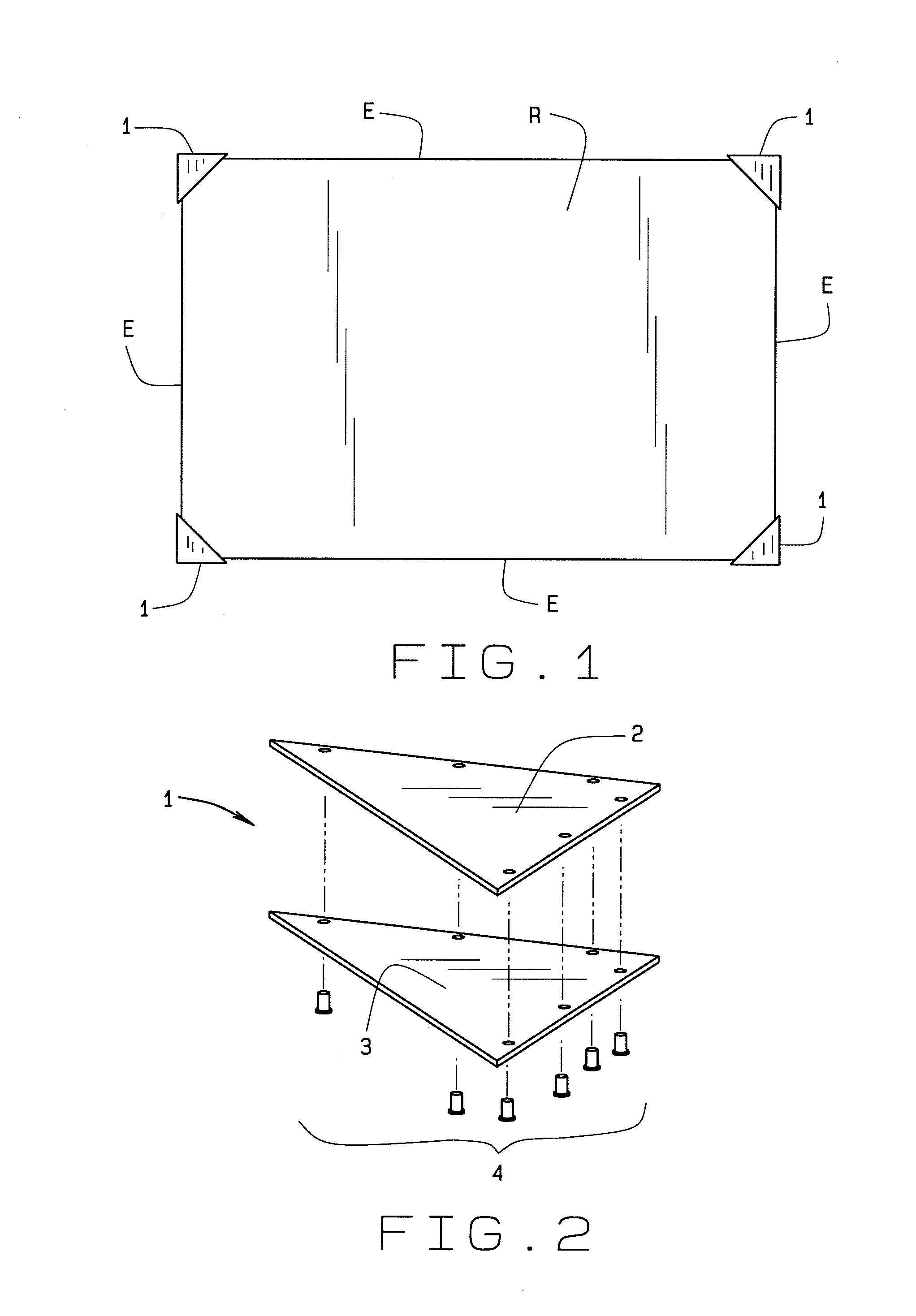
[0032]The present art overcomes the prior art limitations by providing a rug hold down corner, as in FIG. 1, generally part of a kit of four, that overcomes the limitations of prior devices and methods for weighting corners of rugs and mats. The present invention shown in FIG. 1 begins with the invention 1 shown placed upon the four corners of an area rug R. Though rugs R are described, the applicant foresees usage of the invention upon mats. Here the rug has a generally rectangular shape with four of its own corners at the intersection of two edges E. The edges generally intersect at a right angle and have the tip of the intersection, or corner, reinforced using existing rug making methods. Sometimes, the tip of the intersection rises up or curls because of various conditions including humidity, temperature, hygiene, and objects. The curled tip often catches a person's foot, leading to further curling of the rug and disturbance of the gait of a person. To prevent a person catching ...


PUM


Abstract

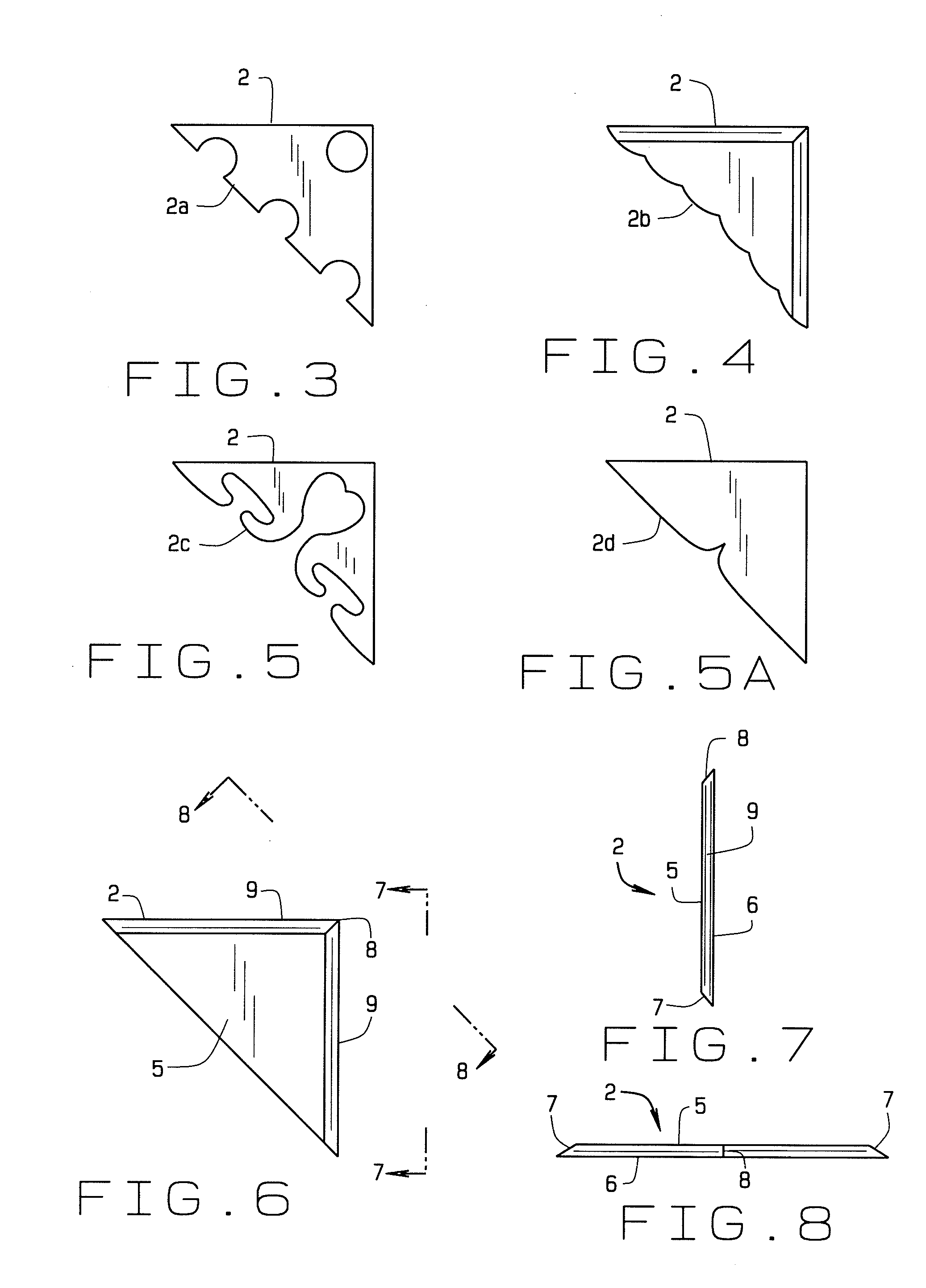
A rug hold down corner has a planar plate connecting to a base beneath. The plate and base have triangular forms, preferably a right triangle and alternatively an isosceles right triangle. The triangular forms include two edges intersecting at a common point and a hypotenuse opposite the common point. The plate connects to the base using mechanical fasteners preferably upon the edges and alternatively upon the interior of the plate and the base. The plate may have various geometric patterns formed therein while the base generally remains solid and includes at least one felt pad, generally opposite the plate. The felt pad contacts a floor surface or other carpet beneath the rug. In a further alternate embodiment, the edges of the plate extend outwardly and downwardly so the edges extend over and down the periphery of a rug's corner.

Description

CROSS-REFERENCE TO RELATED APPLICATION[0001]This non-provisional application claims priority to the pending provisional application 61 / 387,277 filed on Sep. 28, 2010 which is owned by the same inventor.BACKGROUND OF THE INVENTION[0002]The rug hold down corner generally relates to housewares and more specifically to area rug accessories. The invention relates to area rugs placed upon floors generally away from walls. An area rug, or mat, generally has a defined size and finished edges that remain visible when the area rug, or mat, is upon a floor.[0003]Over the centuries, various forms of rugs and floor coverings have sought to protect floors from abrasion, to decorate homes, to muffle sounds, and to protect the inhabitants of a home. Additionally, rugs see use in offices to reflect a certain status. Persian rugs with their intricate woven patterns have been desired for decades. The earliest Persian rug dates to 500 B.C. Rugs have been made from wool, cotton, polyester, and various o...

Claims


Application Information

Patent Timeline
IPC IPC(8): A47G27/00
CPCY10T16/14A47G27/0418
Inventor CRENSHAW, SR., EARLIE LEE
Owner CRENSHAW SR EARLIE LEE
Learn More