Fuel-injection condition detector
a condition detector and fuel injection technology, applied in the direction of machines/engines, electrical control, instruments, etc., can solve the problems of high accuracy, difficult to compute the fuel injection-start timing “r”, and high correlation, and achieve high correlation and high accuracy
- Summary
- Abstract
- Description
- Claims
- Application Information
AI Technical Summary
Benefits of technology
Problems solved by technology
Method used
Image
Examples
first embodiment
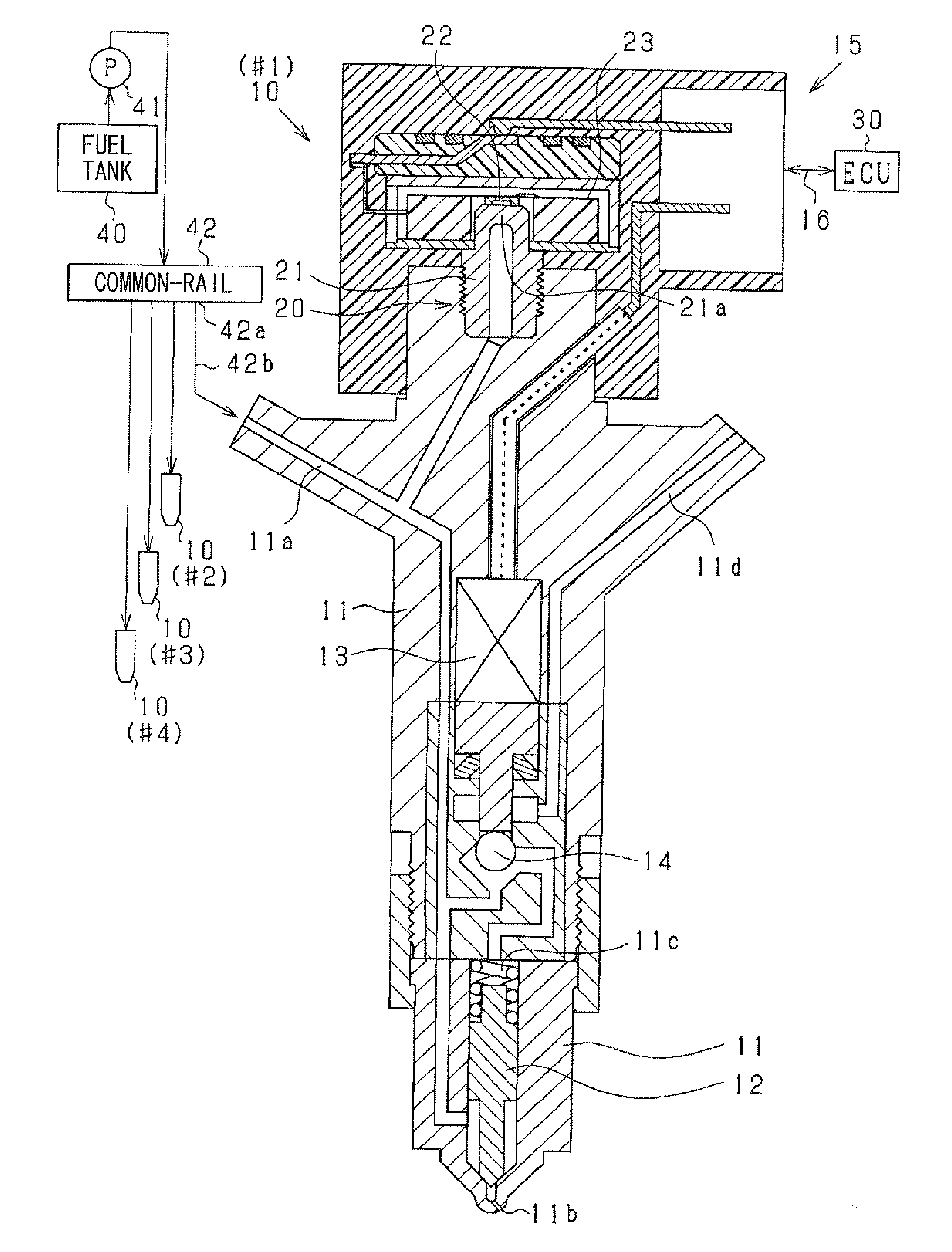
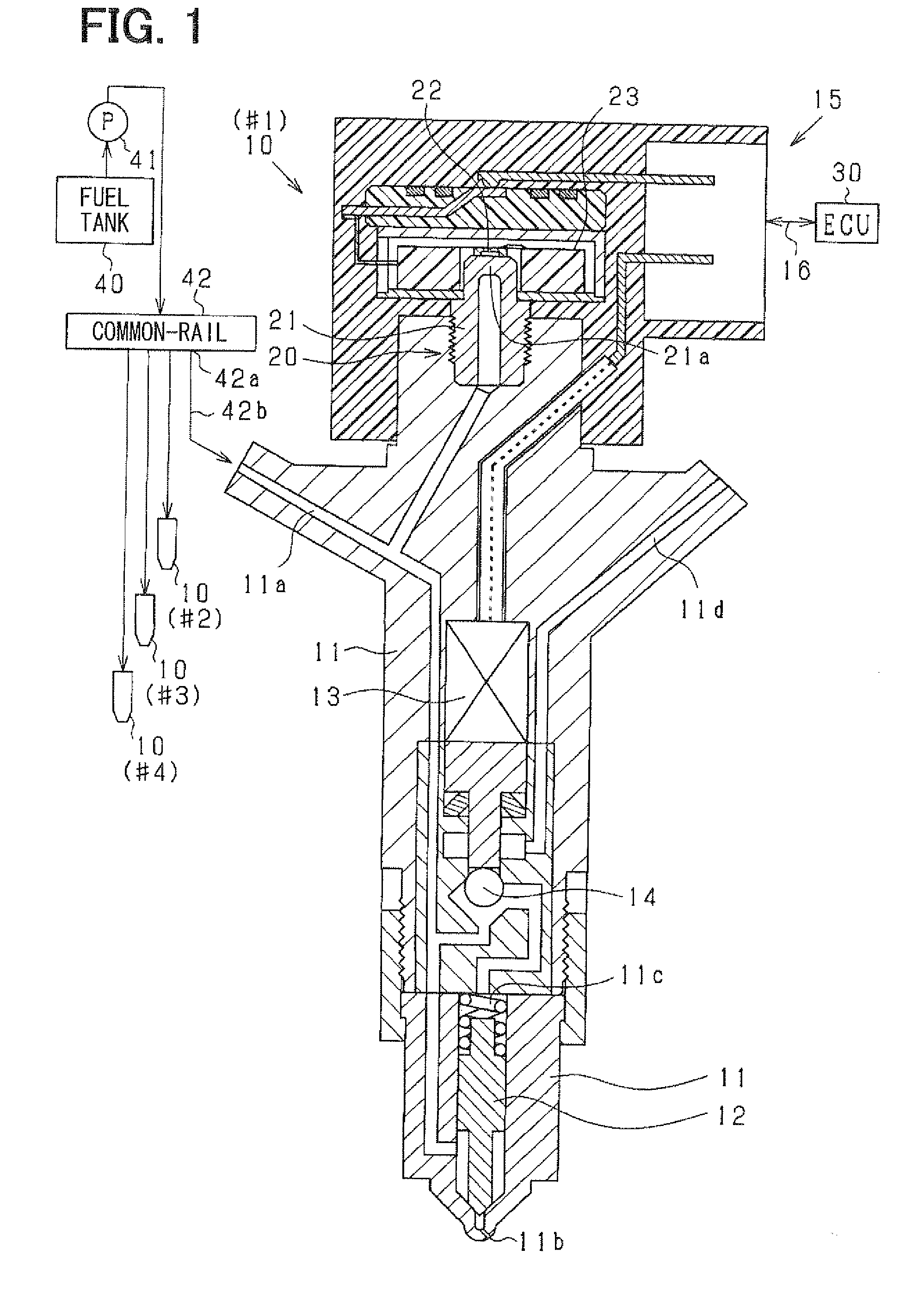
[0038]FIG. 1 is a schematic view showing fuel injectors 10 provided to each cylinder, a fuel pressure sensor 20 provided to each fuel injectors 10, an electronic control unit (ECU) 30 and the like.
[0039]First, a fuel injection system of the engine including the fuel injector 10 will be explained. A fuel in a fuel tank 40 is pumped up by a high-pressure pump 41 and is accumulated in a common-rail (accumulator) 42 to be supplied to each fuel injector 10 (#1-#4). The fuel injectors 10 (#1-#4) perform fuel injection sequentially in a predetermined order. The high-pressure pump 41 is a plunger pump which intermittently discharges high-pressure fuel.
[0040]The fuel injector 10 is comprised of a body 11, a needle valve body 12, an actuator 13 and the like. The body 11 defines a high-pressure passage 11a and an injection port 11b. The needle valve body 12 is accommodated in the body 11 to open / close the injection port 11b.
[0041]The body 11 defines a backpressure chamber 11c with which the h...
second embodiment
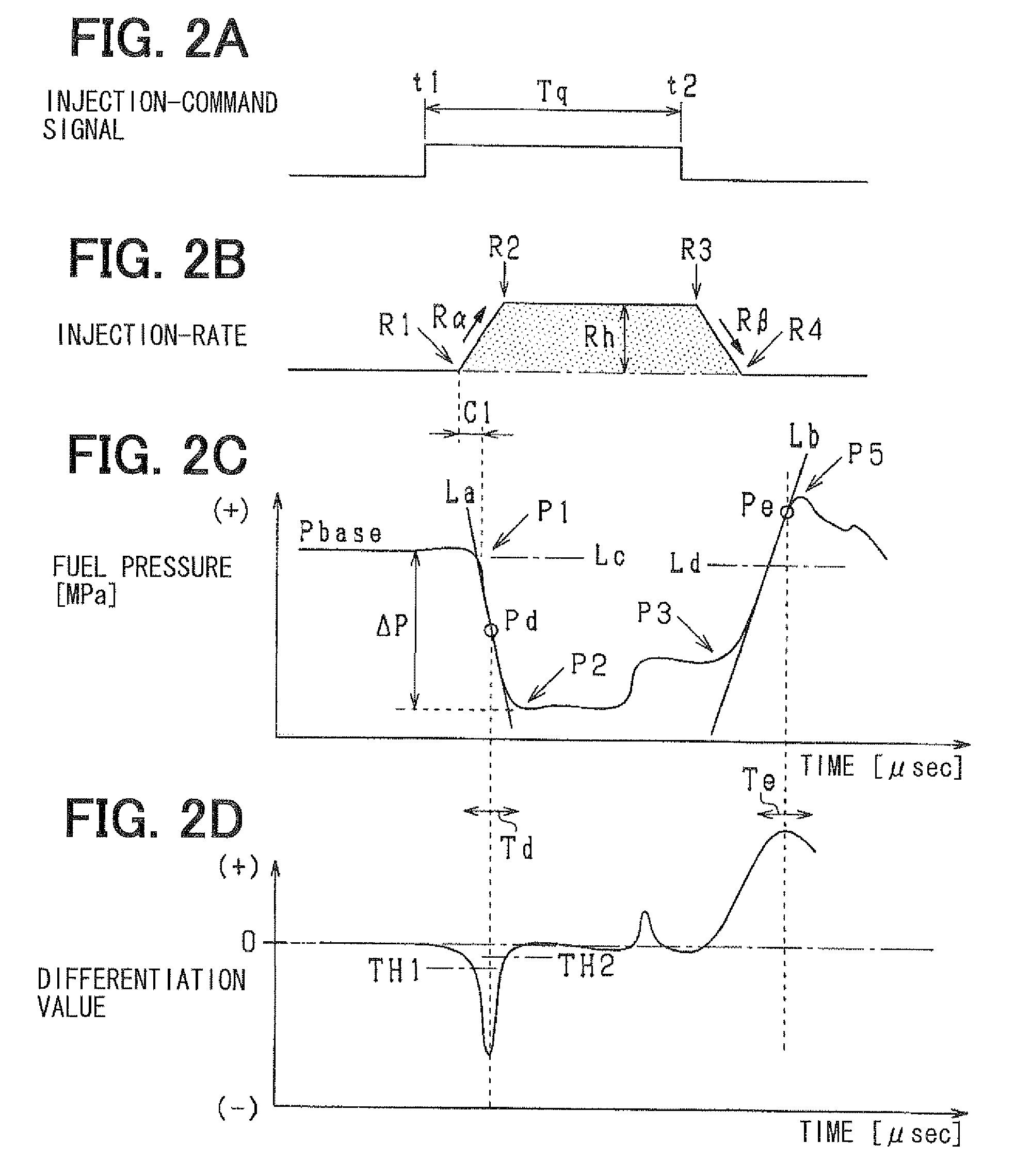
[0072]In the above first embodiment, the weights “w1”-“w11” are computed based on the differences “e1”-“e11” in step S23. According to the second embodiment, the weights “w1”-“w11” are computed based on a time difference between a detection timing of each pressure value “D1”-“D11” and an appearance timing “tPd” of the point “Pd”. In FIG. 6, the weights of the values “D5” and “D6” are greater than those of values “D1”, “D2”, “D10” and “D11”. In FIG. 5A, the weights of the values “Da” and “Db” are greater than those of the values “Dc” and “Dd”.
[0073]FIG. 7 is a flowchart showing a processing for computing an approximated line of a descent pressure waveform. In step S21 and step S22, the pressure values “D1”-“D11” of the descent pressure waveform are approximated to a least-squares approximate line “La1” by least squares method.
[0074]In step S23a (weighting means), the appearance timing “tPd” of the point “Pd” is computed. In step S23b (weighting means), with respect to each value “D1”...
PUM
 Abstract
Description
Claims
Application Information
 - R&D
- Intellectual Property
- Life Sciences
- Materials
- Tech Scout
- Unparalleled Data Quality
- Higher Quality Content
- 60% Fewer Hallucinations
Browse by: Latest US Patents, China's latest patents, Technical Efficacy Thesaurus, Application Domain, Technology Topic, Popular Technical Reports.
© 2025 PatSnap. All rights reserved.Legal|Privacy policy|Modern Slavery Act Transparency Statement|Sitemap|About US| Contact US: help@patsnap.com


