
Worm drive

a technology of worm wheel and worm wheel, which is applied in the direction of gearing, gearing elements, hoisting equipment, etc., can solve the problems of unimproved durability of synthetic resin parts, and achieve the effects of large bending deformation (bending stress), unimproved durability of synthetic resin parts, and increased durability of worm wheels

Inactive Publication Date: 2012-03-22
JTEKT CORP
View PDF18 Cites 10 Cited by
  • Summary
  • Abstract
  • Description
  • Claims
  • Application Information

AI Technical Summary

Benefits of technology

[0010]With the foregoing in view, it is an object of the invention to provide a worm drive that excels in durability and can suppress variations in performance caused by temperature variations.
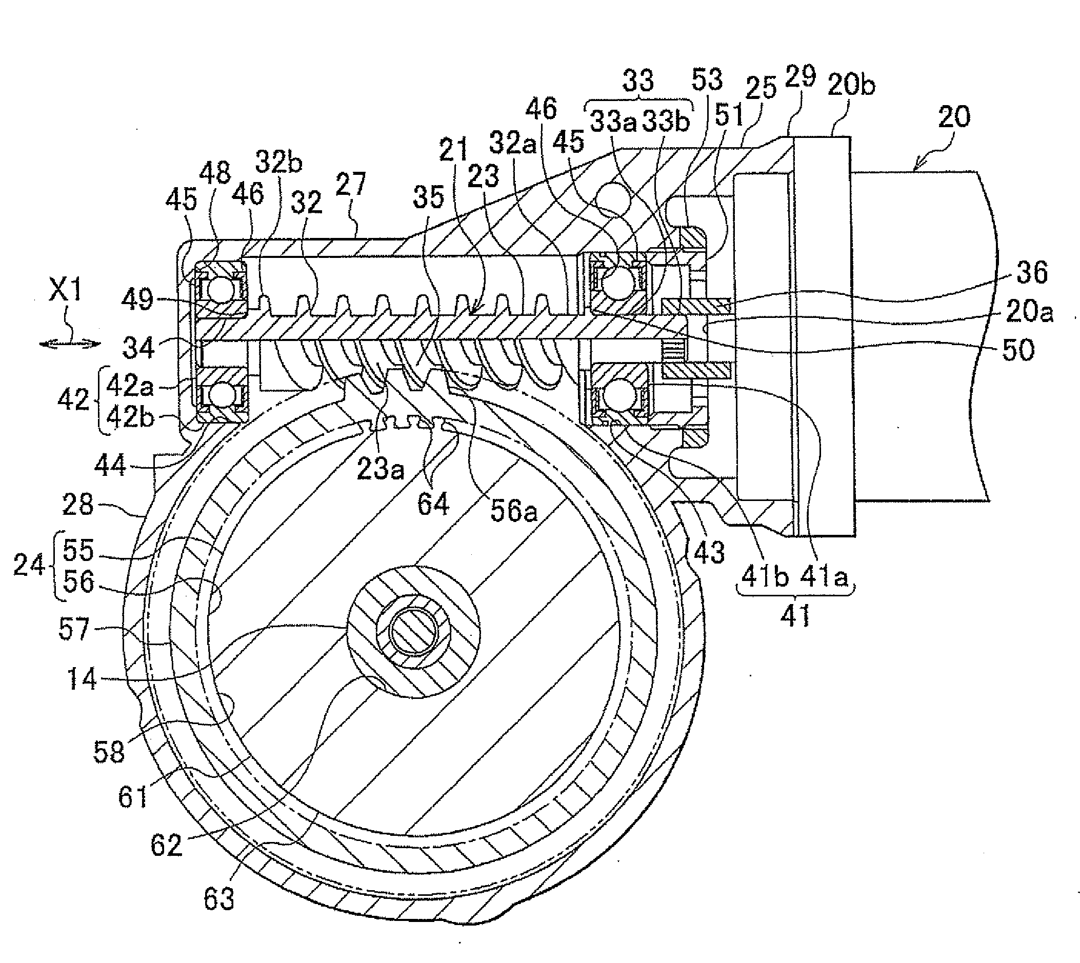
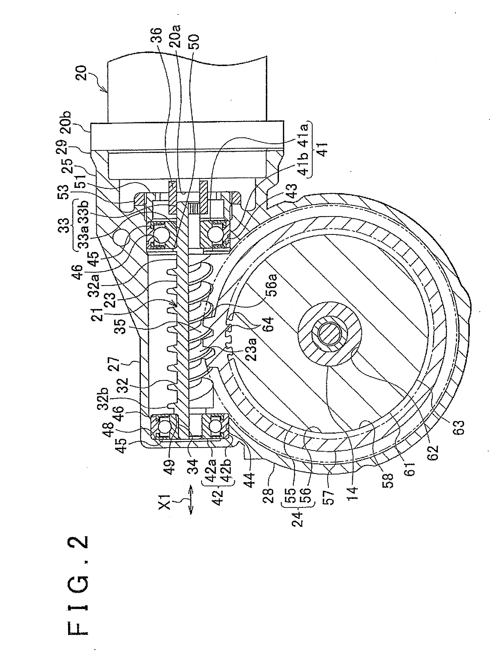
[0013]As a result, the synthetic resin member can be prevented from floating with respect to the core. Therefore, large bending deformation (bending stress) caused by floating of the synthetic resin member can be prevented from occurring in the synthetic resin member. As a result, durability of the worm wheel can be further increased through the reduction of load on the synthetic resin member. Further, durability of the synthetic resin member is not improved by increasing the thickness of the synthetic resin member (thickness in the axial direction of the worm wheel) and increasing the possible elastic deformation of the synthetic resin member. Therefore, the thickness of the synthetic resin member can be decreased and therefore the expansion / contraction amount of the synthetic resin member caused by temperature variations can be reduced. Thus, the backlash amount between the tooth portions of the synthetic resin member and the tooth portions of the worm shaft can be maintained at an adequate value. As a consequence, it is possible to realize the worm drive in which variations in performance caused by temperature variations have been suppressed.
[0014]It is also preferred that, in the aforementioned worm drive, the widening portion include a tapered portion in which the width increases continuously toward the outside in the radial direction. In this case, the inside diameter portion of the synthetic resin member is received by the widening portion, thereby making it possible to prevent more reliably the inside diameter, portion of the synthetic resin member from displacing outward in the radial direction (that is, the occurrence of floating). Therefore, the occurrence of bending deformation in the synthetic resin member can be suppressed more reliably.
[0015]Further, it is also preferred that, in the aforementioned worm drive, an outer contour shape of each of the joining tooth portions include a curved shape, when viewed from an axial direction of the worm wheel. In this case, the occurrence of stress concentration in the inside diameter portion of the synthetic resin member caused by abutment of the joining tooth portions and the inside diameter portion of the synthetic resin member can be suppressed. As a result, a local load can be prevented from acting upon the inside diameter portion of the synthetic resin member. Therefore, durability of the worm wheel can be further increased.
[0016]It is also preferred that, in the aforementioned worm drive, the width of the widening portion increase stepwise toward the outside in the radial direction, and the outer contour shape of each of the joining tooth portions may be formed by a straight line, when viewed from the axial direction of the worm wheel. In this case, the inside diameter portion of the synthetic resin member is also received by the widening portion, thereby making it possible to prevent reliably the inside diameter portion of the synthetic resin member from displacing outward in the radial direction (that is, the occurrence of floating). Therefore, the occurrence of bending deformation in the synthetic resin member can be suppressed more reliably.
[0017]It is also preferred that, in the aforementioned worm drive, the outside diameter portion of the core have an identical cross-sectional shape in any cross section perpendicular to the axial direction of the worm wheel. With such a worm drive, the inside diameter portion of the synthetic resin member can be joined to the joining tooth portions at any position of the worm wheel in the axial direction of the worm wheel. Therefore, bending deformation of the synthetic resin member can be suppressed at any position of the worm wheel in the axial direction of the worm wheel. Further, the synthetic resin member can be formed by injection molding a molten synthetic resin in a die along the axial direction of the core in a state in which the core is inserted into the die. In this case, the molten synthetic resin can be caused to spread uniformly around the outside diameter portion of the core. Therefore, the worm wheel in which the inside diameter portion of the synthetic resin member is in gapless contact with the outside diameter portion of the core can be easily molded. Further, since the cross-sectional shape of the outside diameter portion of the core is constant, the outside diameter portion of the core can be easily formed by drawing or the like.

Problems solved by technology

Further, durability of the synthetic resin member is not improved by increasing the thickness of the synthetic resin member (thickness in the axial direction of the worm wheel) and increasing the possible elastic deformation of the synthetic resin member.

Method used


Image

  • Worm drive
  • Worm drive
  • Worm drive

Examples


first embodiment

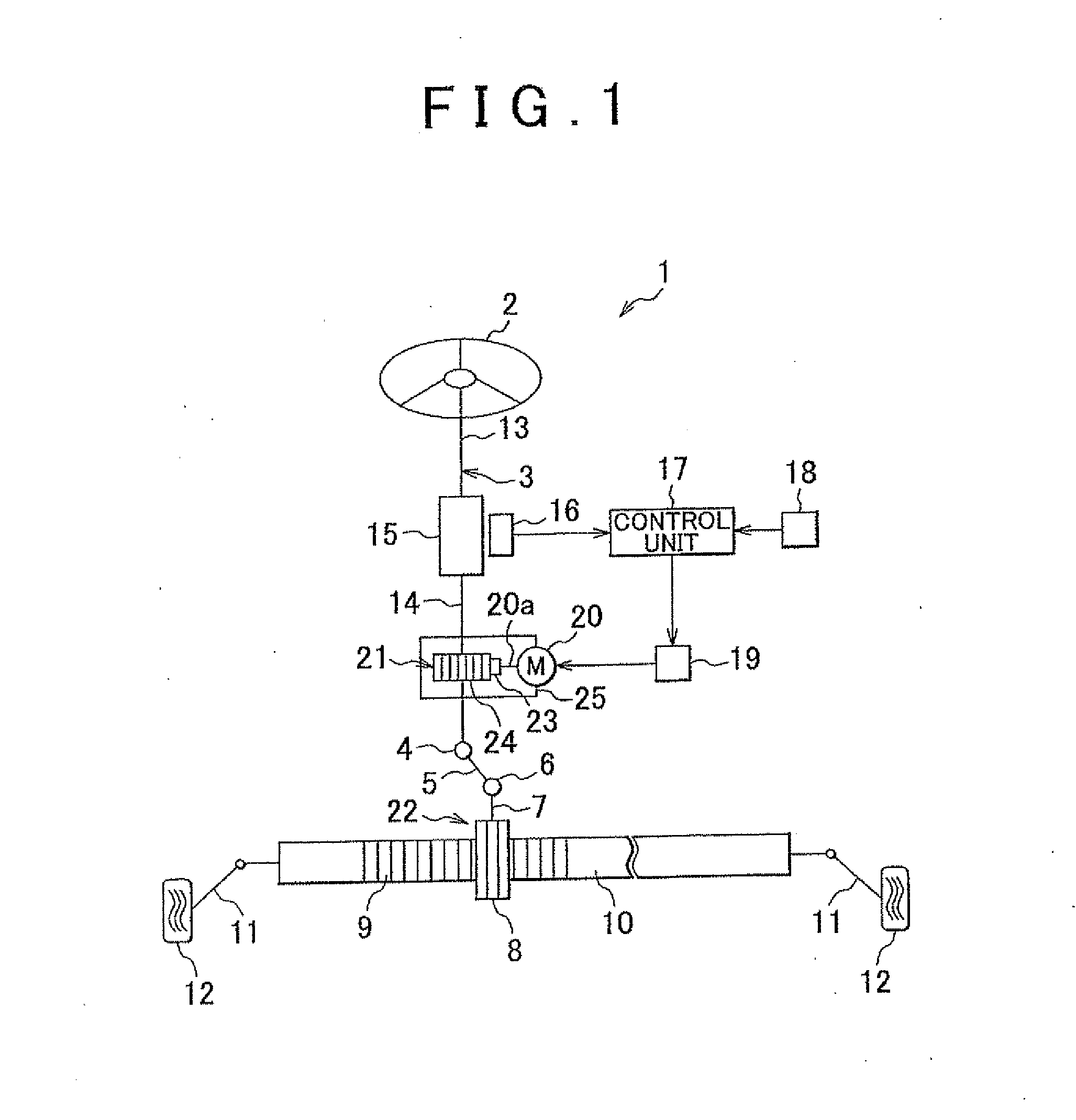
[0025]The preferred embodiments of the invention will be explained below with reference to the appended drawings. FIG. 1 is a schematic diagram illustrating the schematic configuration of the electric power steering apparatus 1 according to the invention. Referring to FIG. 1, the electric power steering apparatus 1 has a steering shaft 3 connected to a steering member 2 such as a steering wheel, an intermediate shaft 5 connected by means of a universal joint 4 to the steering shaft 3, a pinion shaft 7 connected by means of a universal joint 6 to the intermediate shaft 5, and a rack shaft 10. The rack shaft 10 forms a rack 9 that meshes with a pinion 8 provided at a distal end of the pinion shaft 7 and extends in the left-right direction of a vehicle.

[0026]Tie rods 11 are connected to respective ends of the rack shaft 10, and each tie rod 11 is connected to the corresponding steered wheel 12 by means of a corresponding knuckle arm (not shown in the figure). Where the steering member ...

second embodiment

[0058]The invention is not limited to the contents of the above-described embodiments and can be changed variously. For example, the width of the widening portion 64b of the first joining tooth portion 64 in the circumferential direction C1 may increase in a stepwise manner toward the outside in the radial direction R1, as in the core 55 and the synthetic resin member 56 in the invention illustrated by FIG. 5. In this case, the inner circumferential surface of the inside diameter portion 5S of the synthetic resin member 56 is shaped to follow the outer circumferential surface of the outside diameter portion 61 of the core 55.

[0059]Further, the cross-sectional shape of the outside diameter portion 61 of the core 55 of the worm wheel 24 perpendicular to the axial direction of the worm wheel 24 may differ depending on the position in the axial direction. Furthermore, the invention can be applied to apparatuses other than the electric power steering apparatus.


PUM


Abstract

A worm wheel of a worm drive includes an annular synthetic resin member having tooth portions meshing with a worm shaft and a core having an outside diameter portion joined to an inside diameter portion of the synthetic resin member. The outside diameter portion of the core has first joining tooth portions that protrude outward in a radial direction and are joined to the inside diameter portion of the synthetic resin member. Each of the first joining tooth portions includes a widening portion whose width in a circumferential direction increases toward the outside in the radial direction.

Description

INCORPORATION BY REFERENCE[0001]The disclosure of Japanese Patent Application No. 2010-210936 filed on Sep. 21, 2010 including the specification, drawings and abstract is incorporated herein by reference in its entirety.BACKGROUND OF ME INVENTION[0002]1. Field of the Invention[0003]The invention relates to a worm drive.[0004]2. Description of Related Art[0005]An electric power steering apparatus is usually provided with a worm drive for transmitting output of an electric motor to a steering mechanism. For example, in Japanese Patent Application Publication No. 2006494296 (JP-A-2006-194296), a worm drive includes a worm shaft connected to an electric motor and a worm wheel connected to a steering shaft. FIG. 6 shows the schematic configuration of a worm drive 100 similar to the worm drive described in JP-A-2006-194296; this figure shows the cross section perpendicular to the central axial line of the worm wheel (see JP-A-2006-194296, paragraphs [0029] and [0030] and FIGS. 7 and 8). R...

Claims


Application Information

Patent Timeline
IPC IPC(8): F16H1/16F16H55/17F16H55/06
CPCF16H55/06Y10T74/19828F16H2055/065F16H55/22
Inventor KIKUCHI, ARATA
Owner JTEKT CORP
Learn More