Fire Resistant Steel Structure

Inactive Publication Date: 2012-03-22
ARCELORMITTAL INVESTIGACION Y DESARROLLO SL
View PDF5 Cites 3 Cited by
  • Summary
  • Abstract
  • Description
  • Claims
  • Application Information

AI Technical Summary

Benefits of technology

[0012]It will be appreciated that such an emergency backup support system will—by providing an external, collapse retarding catenary support mechanism for the overheated steel beam—substantially increase the time during which a bare steel beam maintains its load bearing function when it is overheated in case of a fire. It follows that a costly and time consuming application of a fireproof insulation onto the steel beam is not necessary, and that a bare steel beam (i.e. a steel beam without fireproof insulation or concrete encasement) may maintain its load bearing function in case of a fire at least as long as a heavy composite steel beam (i.e. a steel beam with a partial or full concrete encasement).
[0016]It will further be appreciated that efficiently using an inherently fire resistant tension member or protecting a slender tension member with a fireproof heat insulation is by far easier, less costly and less time-consuming than applying such a fireproof heat insulation to the steel beam itself. Furthermore, such fire-resistant tension members result in a smaller surcharge of the support structure than a partially encased composite steel beam (with reinforced concrete between the flanges).
[0020]In an alternative embodiment, the emergency backup support system for the steel beam includes at least one fire-resistant tension member arranged transversally to the steel beam. When the overheated steel beam yields in this embodiment, it rests on the at least one transverse fire-resistant tension member, e.g. directly with its lower flange or by means of an intermediate support member. Such a solution with at least one fire-resistant tension member arranged transversally to the steel beam may be of particular advantage in combination with a cellular steel beam having apertures in its web. This is because a transverse fire-resistant tension member does not impede the passage of conduits through the apertures in its web of the cellular steel beam.
[0021]Preferably, the at least one fire-resistant tension member is only slightly pre-stressed when the steel beam is cold, so as to have a sufficient reserve for supporting the overheated steel beam. Under the maximum load of the cold beam, the prestress tension in the at least one fire-resistant tension member should preferably not exceed 25%, more preferably not more than 15% of the tensile strength of the tension member. The slight prestress tension shall e.g. warrant that there is no substantial play in the anchoring of the ends of the fire-resistant tension member and that the tension member is already in close contact with beam when a fire breaks out, i.e. that the at least one fire-resistant tension member is capable of developing a catenary support mechanism for the overheated beam as soon as the latter begins to yield in case of a fire. It is however to be noted that the fire-resistant tension member does not need to play a structural role in the cold state so that it does not need to be pre-stressed. This greatly facilitates the installation of such tension members.
[0022]In order to increase the fire resistance of existing steel structures, this system is very suitable to be applied for two reasons. First, the installation is easy since it requires neither complicate erection phases nor pre-stressing technology. Second, since it is active only in fire condition, it does not require changing the statical functionality of the structure in cold condition.
[0024]The steel beam is preferably supported by the support structure in such a way that it may axially expand when heating up under severe fire conditions, whereby excessive compressive axial forces in the beam, which may cause a buckling of the latter, are avoided.

Problems solved by technology

These fireproof insulations must generally be applied in-situ to all load bearing structural steel components, which is a costly and time-consuming operation.
However, they are also much heavier than bare steel profiles, which is a substantial disadvantage, in particular for horizontal load bearing structural steel members, as e.g. beams and girders.

Method used


Image

  • Fire Resistant Steel Structure
  • Fire Resistant Steel Structure
  • Fire Resistant Steel Structure

Examples


Embodiment Construction

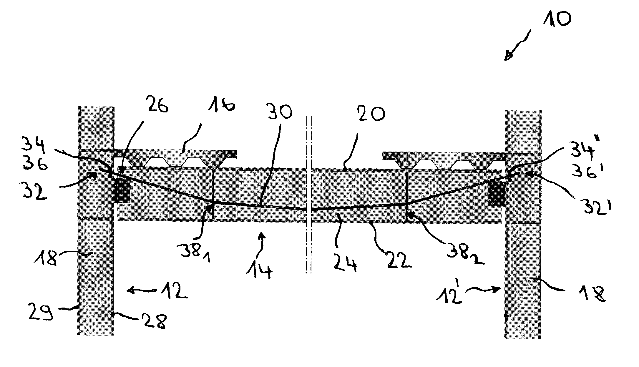
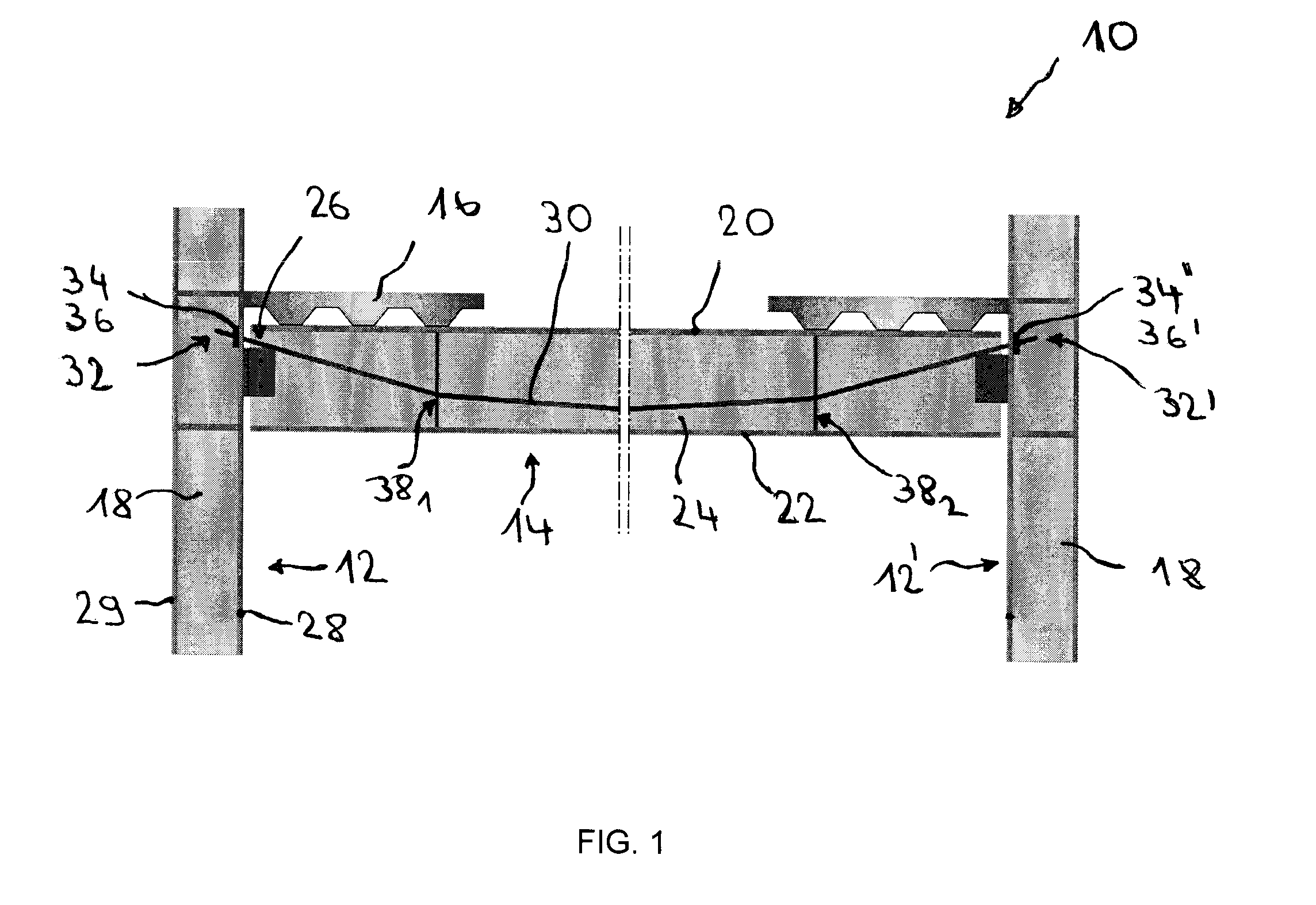
[0042]FIG. 1 shows a fire resistant steel structure 10 in accordance with the invention. This steel structure 10 comprises two columns 12, 12′ (i.e. vertical structural members) forming a support for a steel beam 14 (i.e. a horizontal structural member) at two horizontally spaced locations. The steel beam 14 serves as support element for a slab 16, in this case e.g. a concrete slab with profiled steel sheets.

[0043]The columns 12, 12′ shown in FIG. 1 are H-shaped steel beams with a reinforced concrete filling 18 between the flanges (such columns are generally called composite columns). The reinforced concrete filling 18 warrants that the columns 12, 12′ maintain their load bearing function during the required time of fire exposure. Alternatively, the columns 12, 12′ might also be steel profiles protected with a fireproof casing made e.g. of silicate or gypsum plates with or without mineral fiber insulations, with spray applied fireproofing materials, intumescent paints or coatings, r...


PUM


Abstract

A fire resistant steel structure (10) comprises a steel beam (14) for receiving a vertical load and a support structure for supporting the horizontal beam (14) at two horizontally spaced locations. At least one fire-resistant tension member (30) has its ends (32, 32′) anchored outside the steel beam (14) in the support structure. It is arranged relative to the steel beam (14) in such a way that when the steel beam (14) is overheated and yields under the vertical load in case of severe fire conditions, it rests on the at least one fire-resistant tension member (30) and is vertically supported by the latter.

Description

TECHNICAL FIELD[0001]The present invention generally relates to a fire resistant steel structure.BACKGROUND ART[0002]Unprotected structural steel members like columns, girders, beams etc. lose most of their load bearing capacity when they are exposed to temperatures above 400 C. For warranting the required fire resistance rating in multistorey steel structures, it is well known in the art to use a fireproof heat insulation slowing down temperature rise in load bearing structural steel components. Known heat insulation measures comprise e.g.: fireproof encasements with slab-type materials made e.g. from calcium silicate or gypsum; mineral fiber insulations; spray applied fireproofing materials and intumescent paints or coatings. These fireproof insulations must generally be applied in-situ to all load bearing structural steel components, which is a costly and time-consuming operation.[0003]It is also known to use composite profiles, i.e. steel profiles with a partial or full concrete...

Claims


Application Information

Patent Timeline
IPC IPC(8): E04C3/04E04C3/30E04B1/94
CPCE04B1/24E04B1/94E04C2003/0452E04B5/40E04C3/10E04B1/945
Inventor CAJOT, LOUIS-GUYZANON, RICCARDO
Owner ARCELORMITTAL INVESTIGACION Y DESARROLLO SL
Why Eureka
Try Eureka