
Digital imaging system, plenoptic optical device and image data processing method

a digital imaging and optical device technology, applied in the field of digital imaging systems, can solve problems such as and achieve the effect of avoiding disadvantages of conventional plenoptic imaging techniques

Active Publication Date: 2012-03-01
RAYTRIX
View PDF10 Cites 152 Cited by
  • Summary
  • Abstract
  • Description
  • Claims
  • Application Information

AI Technical Summary

Benefits of technology

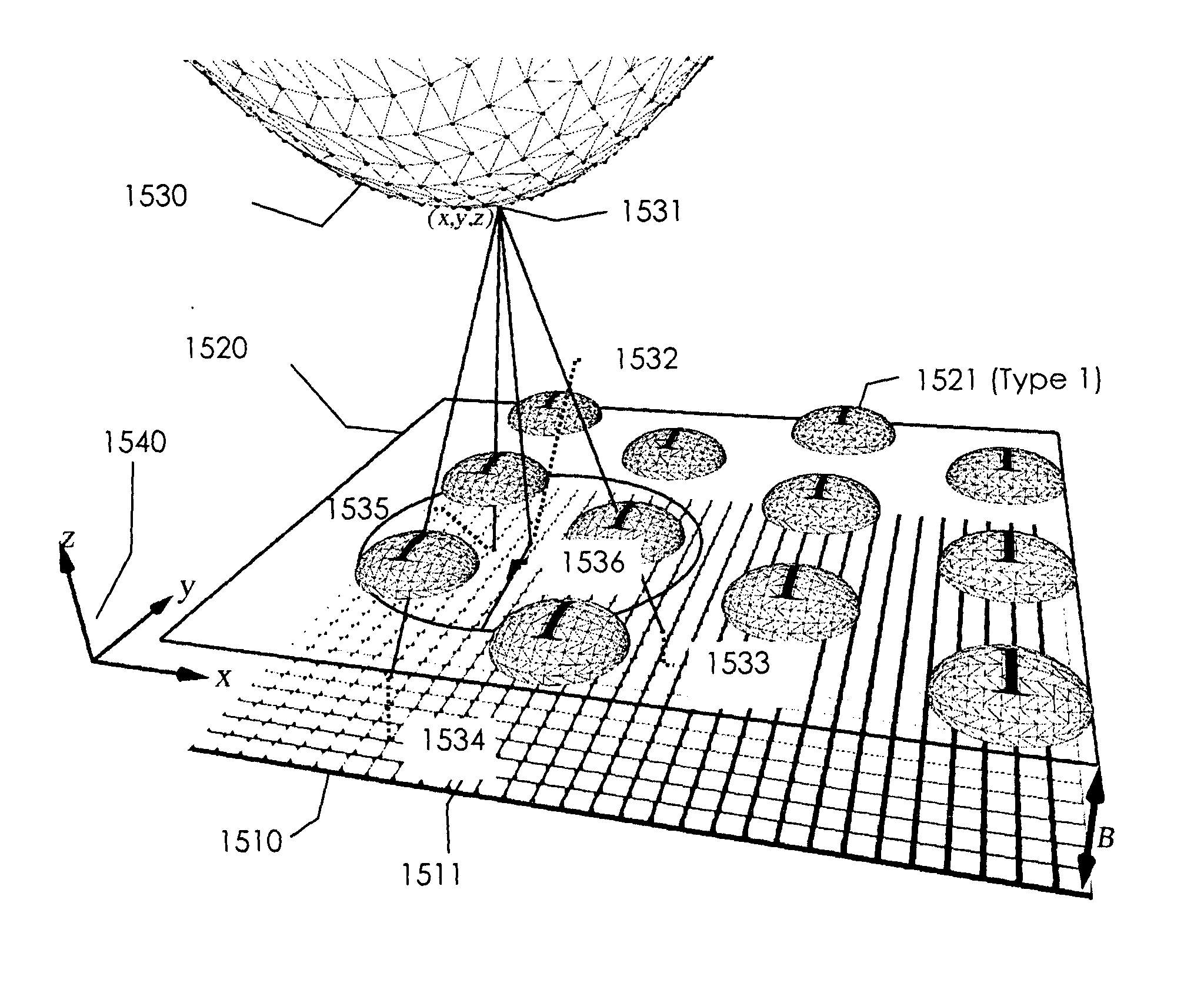
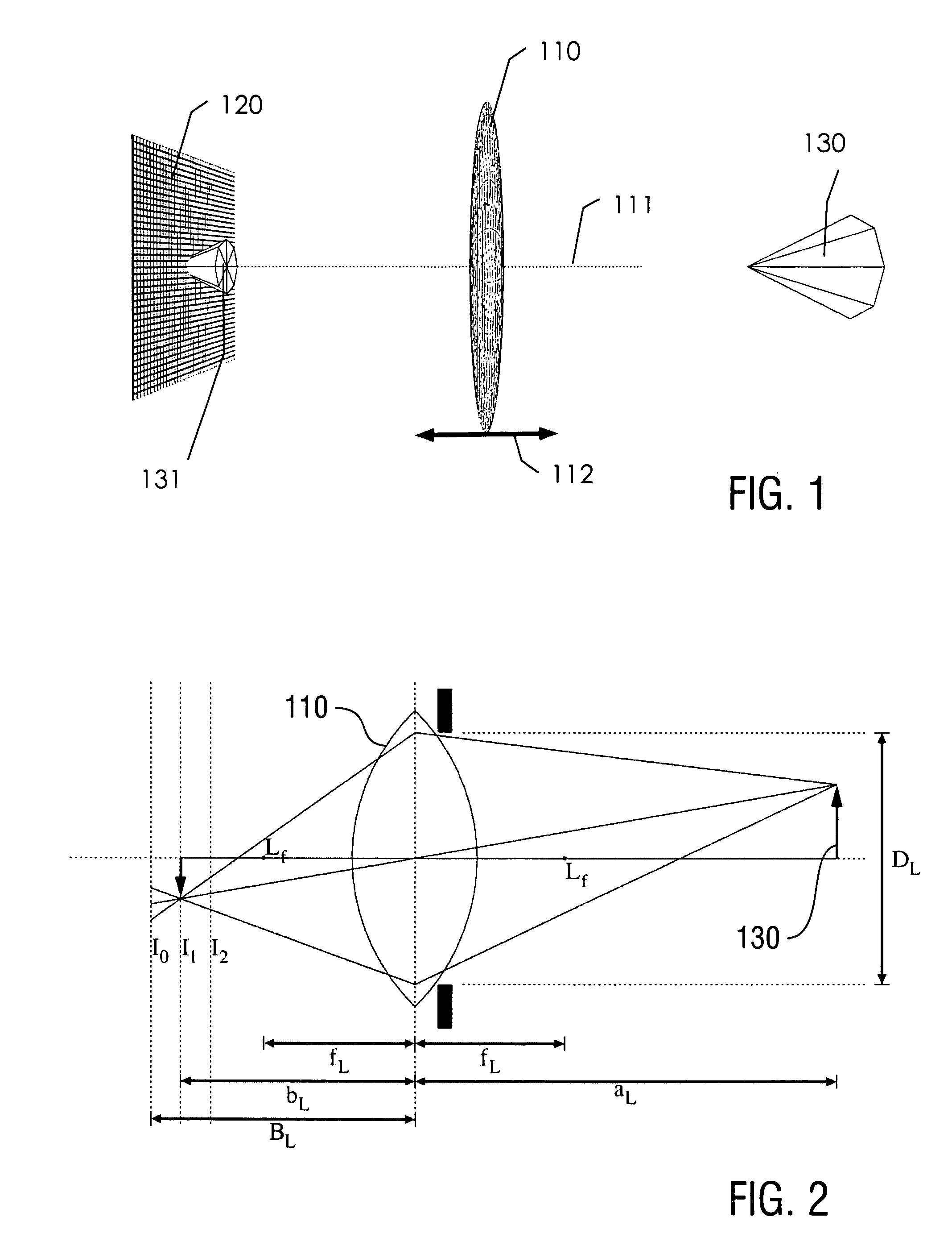
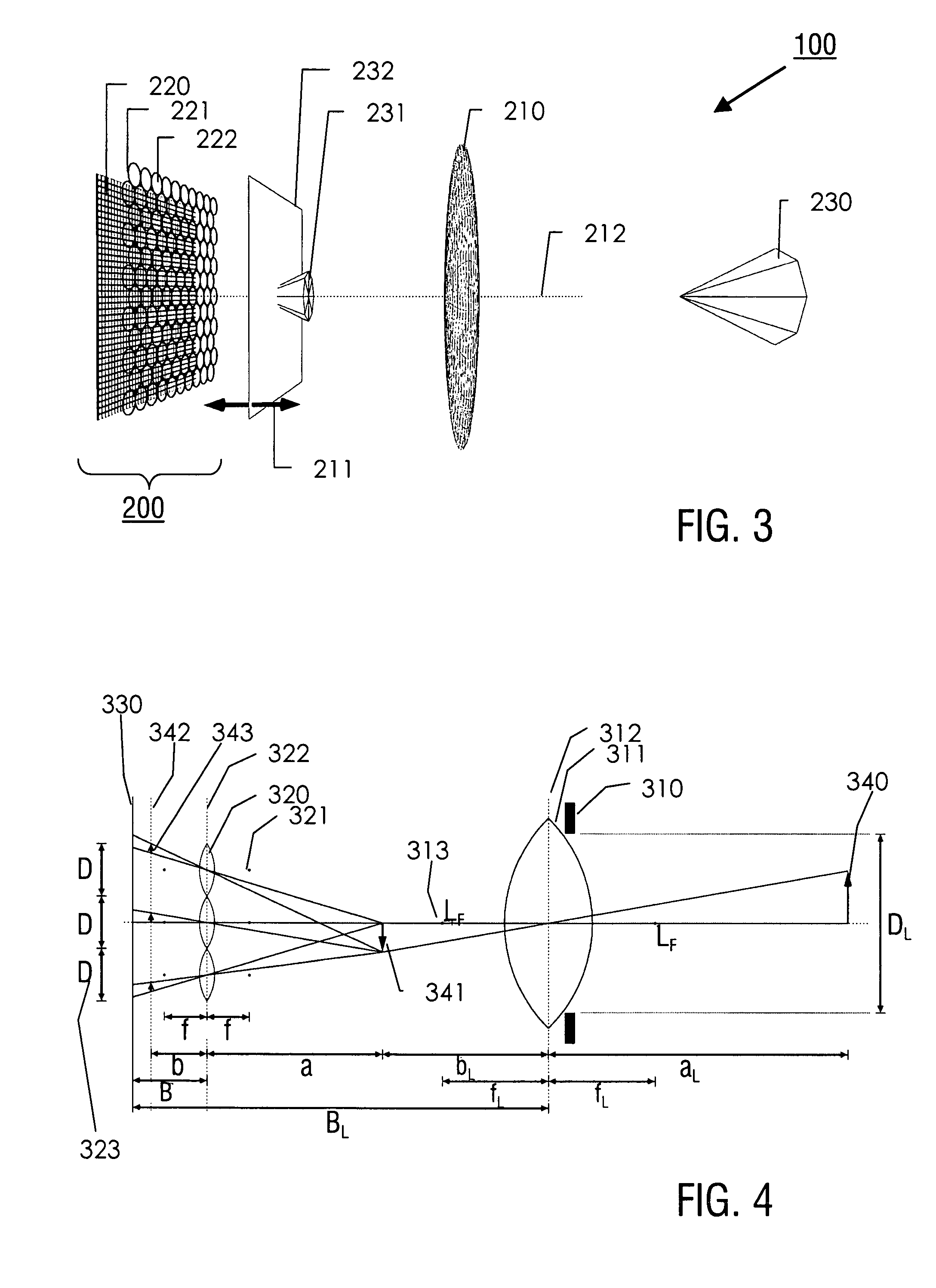
[0009]With the above combination of features, the following technical effects are obtained with the inventive digital imaging system. Firstly, due to the deviation of the focal length of any of the microlenses from the image plane—microlens distance, a virtual image at a finite distance from the microlenses is imaged onto the image plane, contrary to the imaging of a virtual image at an infinite distance with the conventional plenoptic camera. The microlenses are used for imaging with a finite focal depth. This limitation is compensated by the provision of the microlenses with different focal lengths, which allow covering a large focal depth range. Additionally and as shown by the inventor for the first time, imaging of the virtual image at the finite distance provides an improved resolution compared with the conventional camera.
[0020]According to a further preferred embodiment of the digital imaging system all microlenses having a common focal length have the same lens diameter. Particularly preferred is an embodiment wherein all microlenses of the microlens array have the same diameter. With these embodiments, the formation of an image with image parameters, e.g resolution or contrast, being homogeneous over the 2D image is improved.

Problems solved by technology

Firstly, due to the deviation of the focal length of any of the microlenses from the image plane—microlens distance, a virtual image at a finite distance from the microlenses is imaged onto the image plane, contrary to the imaging of a virtual image at an infinite distance with the conventional plenoptic camera.

Method used


Image

  • Digital imaging system, plenoptic optical device and image data processing method
  • Digital imaging system, plenoptic optical device and image data processing method
  • Digital imaging system, plenoptic optical device and image data processing method

Examples


Embodiment Construction

[0033]Preferred embodiments of the invention are described in the following with reference to a digital imaging system and a plenoptic camera provided with the digital imaging system. It is emphasized that the implementation of the invention is not restricted to the illustrated examples, but rather possible with other plenoptic optical apparatuses, like optical scanning devices or microscopes. In the case of an optical scanning device, the photosensor array, typically a line array, is replaced by the inventive digital imaging device, in particular by the combination of a photosensor array and a microlens array. In this case, a main lens, which will be mentioned in the following with reference to the plenoptic camera is provided by scanner optics (cylindrical scanner lens). The microscope application includes replacing the photosensor array of a microscope by the inventive digital imaging device. In this case, the virtual image generated by the main lens in the plenoptic camera is ge...


PUM


Abstract

A digital imaging system being configured for synthesizing an image of a plenoptic optical device, comprises a photosensor array comprising a plurality of photosensors arranged in a predetermined image plane, and a microlens array comprising a plurality of microlenses arranged for directing light from an object to the photosensor array, wherein the photosensor array and the microlens array are arranged with a predetermined distance, the microlenses have different focal lengths varying over the microlens array, and the image plane of the photosensor array is arranged such that the distance between the photosensor array and the microlens array does not equal the microlenses' focal lengths. Furthermore, a plenoptic optical device including the digital imaging system and a method for processing image data collected with the digital imaging system are described.

Description

FIELD OF THE INVENTION[0001]The present invention relates to a digital imaging system being configured for synthesizing an image of a plenoptic optical device (e.g. plenoptic camera). Furthermore, the present invention relates to an optical device, like e.g. a camera device, a scanning device, or a microscope device including the digital imaging system. Furthermore, the present invention relates to a method for processing image data collected with the digital imaging system. In particular, this invention relates to a system employing a camera for Radiance Photography (plenoptic camera) and a method to use it to produce and display pictures with varying depths of sharpness.TECHNICAL BACKGROUND[0002]A plenoptic camera (light field camera) is a camera which is capable of sampling a light distribution and light directions in a light field. On the basis of this information, images can be collected with increased focal depth and / or images can be digitally refocused. In a standard plenopti...

Claims


Application Information

Patent Timeline
IPC IPC(8): H04N5/225H04N5/228
CPCH04N13/0232H04N5/2254G02B27/0075G02B3/0056H04N13/232
Inventor PERWASS, ULRICHPERWASS, CHRISTIAN
Owner RAYTRIX
Learn More