
Diplexer, and resonator filters combined with dual mode and triple-mode resonators

a technology of resonators and filters, applied in the direction of resonators, waveguides, electrical equipment, etc., can solve the problems of reducing the size of filters and the performance standard of filters may not be satisfied

Inactive Publication Date: 2012-03-01
ELECTRONICS & TELECOMM RES INST
View PDF4 Cites 46 Cited by
  • Summary
  • Abstract
  • Description
  • Claims
  • Application Information

AI Technical Summary

Benefits of technology

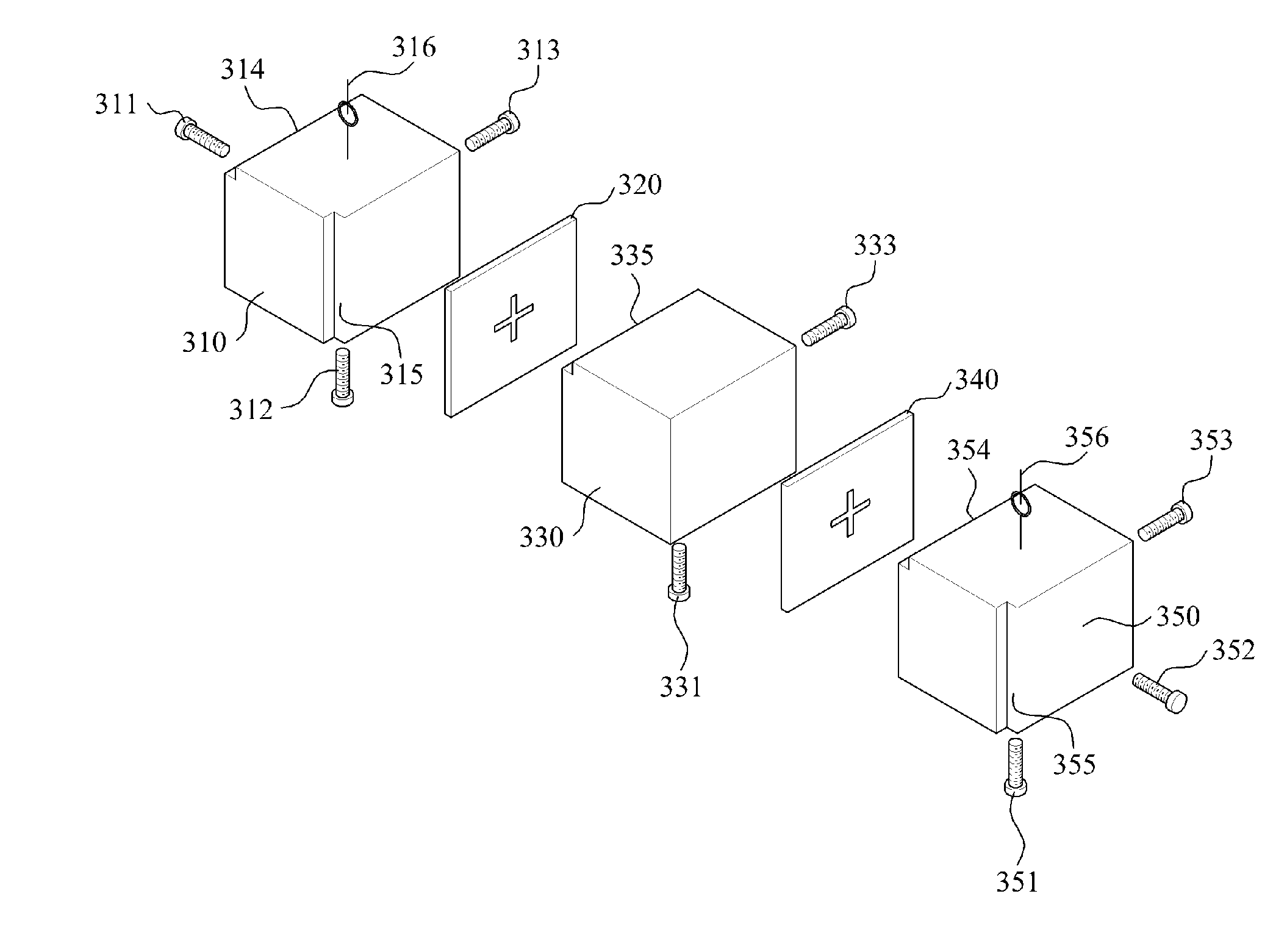
[0011]According to an embodiment of the present invention, it is possible to dispose adjusting portions on perpendicular surfaces to adjust a resonant frequency of each resonant mode, by alternately using a dual-mode resonator and a triple-mode resonator having similar shapes.
[0012]According to another embodiment of the present invention, it is possible to correct an error occurring during a design and a manufacture of a filter by employing an adjusting portion that may adjust a resonant frequency according to each resonant mode.
[0013]According to still another embodiment of the present invention, it is possible to correct an error after manufacturing a resonator filter by disposing a connecting portion between resonances.

Problems solved by technology

In general, a relatively large number of resonators may be used for a filter to construct a filter having a relatively high rejection characteristic, and using a single-mode resonator may be an issue of reducing a size of a filter.
However, since a frequency-response characteristic may be responsive to various errors when a filter is constructed, a distortion of a frequency characteristic due to a designing tolerance, manufacturing tolerance, and the like may directly affect a performance of a filter, and a performance standard of a filter may not be satisfied due to a relatively small error.

Method used


Image

  • Diplexer, and resonator filters combined with dual mode and triple-mode resonators
  • Diplexer, and resonator filters combined with dual mode and triple-mode resonators
  • Diplexer, and resonator filters combined with dual mode and triple-mode resonators

Examples


Embodiment Construction

[0021]Hereinafter, reference will now be made in detail to exemplary embodiments of the present invention, examples of which are illustrated in the accompanying drawings, wherein like reference numerals refer to the like elements throughout. Exemplary embodiments are described below to explain the present invention by referring to the figures. A “resonator filter” described below may refer to a cavity resonator filter.

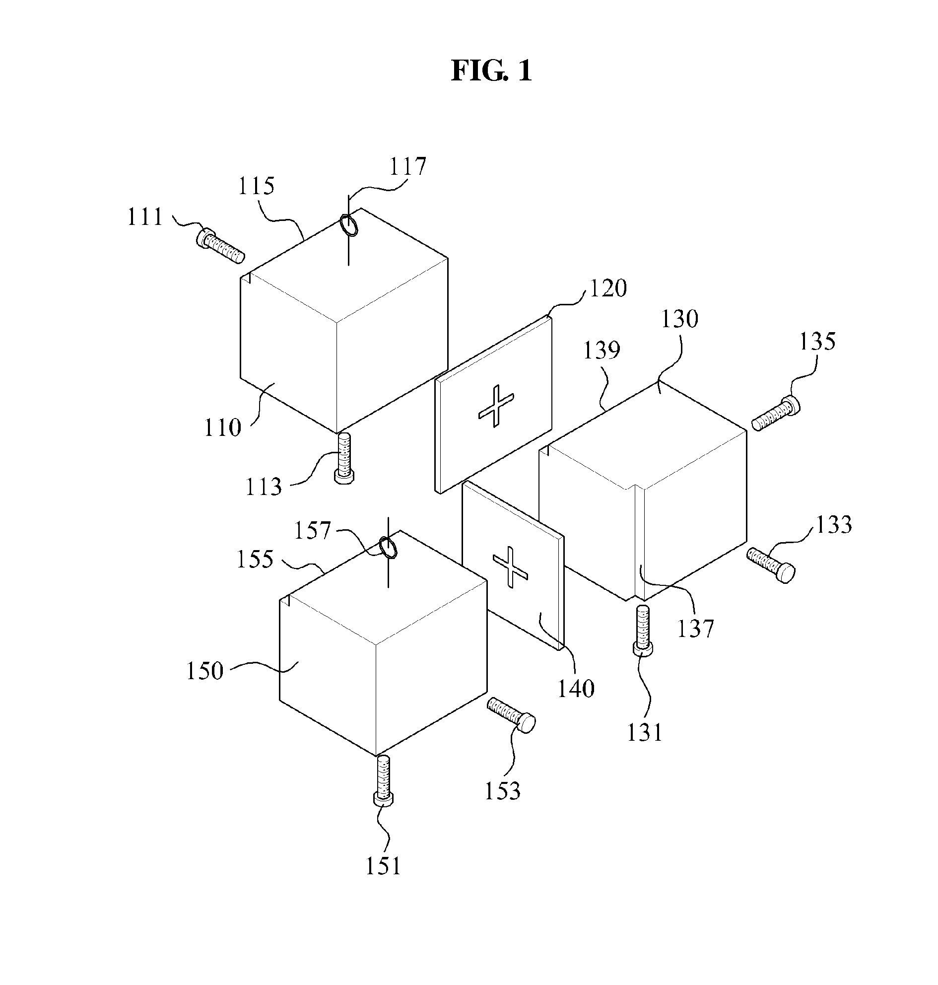
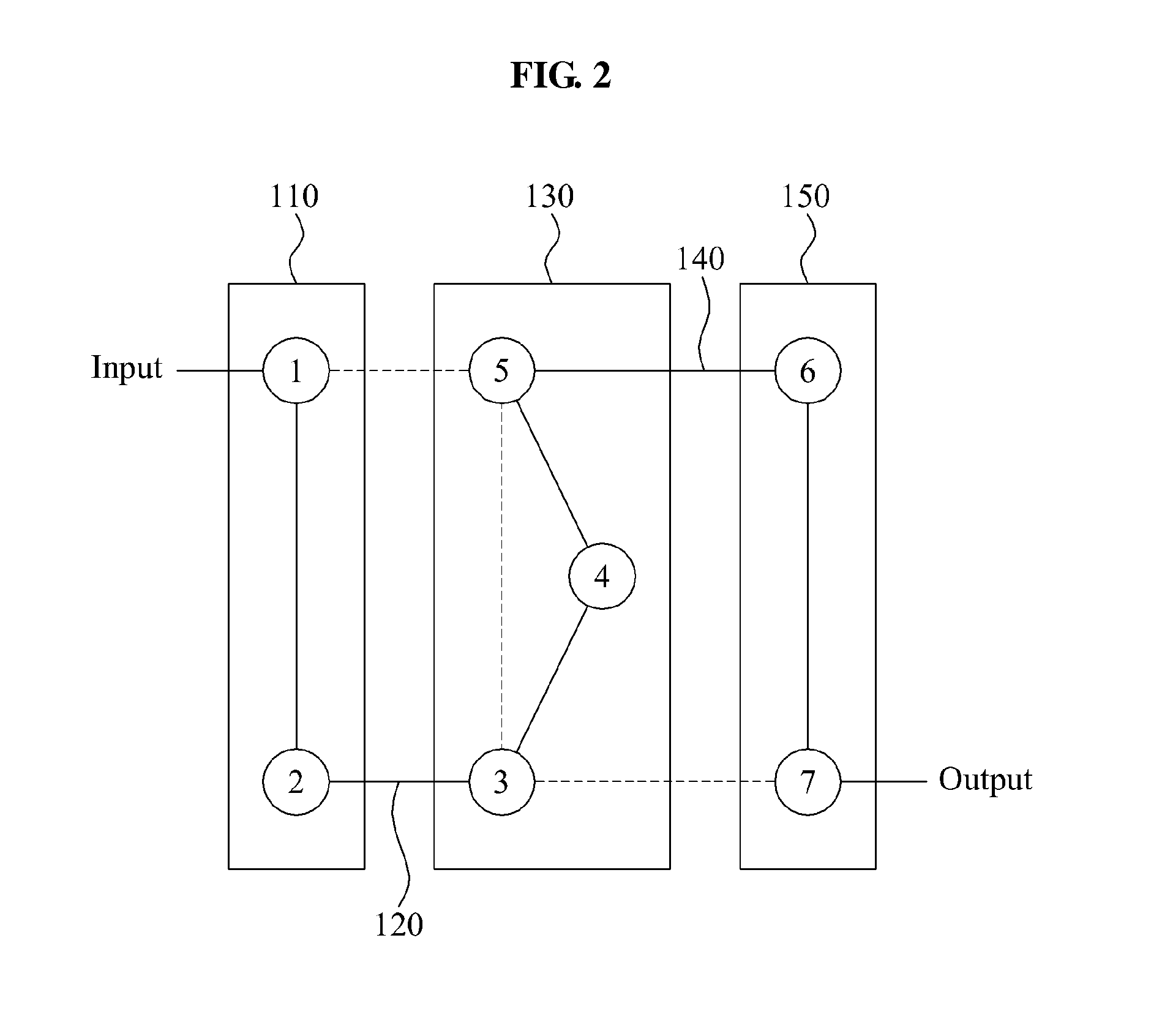
[0022]FIG. 1 is a diagram illustrating a shape of a 7-pole resonator filter including two dual-mode resonators and a single triple-mode resonator according to an embodiment of the present invention, and FIG. 2 is a diagram illustrating an electrical configuration of the 7-pole resonator filter of FIG. 1.

[0023]Referring to FIG. 1 and FIG. 2, the 7-pole resonator filter may include a first dual-mode resonator 110, a first connecting portion 120, for example, a coupling iris, a triple-mode resonator 130, a second dual-mode resonator 140, and a second connecting portion 15...


PUM


Abstract

A 7 pole resonator filter including a dual mode resonator and a triple mode resonator may include a first dual mode resonator including independent adjusting portions adjusting each frequency according to two resonant modes, and having at least one conductive surface, a triple mode resonator including independent adjusting portions adjusting each frequency according to three resonant modes separate from the two resonant modes, and having at least one conductive surface, a first connecting portion electrically connecting the first dual mode and the triple mode resonators, a second dual mode resonator including independent adjusting portions adjusting each frequency according to two resonant modes separate from the two resonant modes and the three resonant modes, and having at least one conductive surface, and a second connecting portion electrically connecting the triple mode resonator and the second dual mode resonator. The three dual mode resonators have similar shapes.

Description

FIELD OF THE INVENTION[0001]The present invention relates to a diplexer, and resonator filters including a dual-mode resonator and a triple-mode resonator.BACKGROUND ART[0002]A filter that only selects a signal of a desired frequency band may be one of indispensable parts of a wireless communication system, and may be one of factors that to hinder miniaturization and cost cutting of the wireless communication system. As the filter used in the wireless communication system, a filter using a lumped element, a micro-strip or strip line filter using a transmission line, a resonator filter, a waveguide filter, a surface acoustic wave (SAW) filter, and the like may be given.[0003]Among the aforementioned various filters, the resonator filter using a cavity that includes a dielectric is mainly used in a microwave band due to a relatively high performance.[0004]A cavity resonator filter may have an appropriate number of resonators and an appropriate combination of structures so as to obtain...

Claims


Application Information

Patent Timeline
IPC IPC(8): H01P1/208
CPCH01P1/2086H01P7/105H01P1/2138
Inventor UHM, MAN SEOKKWAK, CHANG SOOYUN, SO HYEUNCHOI, JANG SUPYOM, IN BOK
Owner ELECTRONICS & TELECOMM RES INST
Learn More