
Method and Apparatus for Cutting High Quality Internal Features and Contours

a technology of internal features and contours, applied in plasma welding apparatus, welding apparatus, manufacturing tools, etc., can solve problems such as leaving behind defects such as divots, and achieve the effects of improving the cut quality, improving the cut quality of a small internal part feature, and maintaining productivity and cutting quality

Active Publication Date: 2012-03-01
HYPERTHERM INC
View PDF4 Cites 1 Cited by
  • Summary
  • Abstract
  • Description
  • Claims
  • Application Information

AI Technical Summary

Benefits of technology

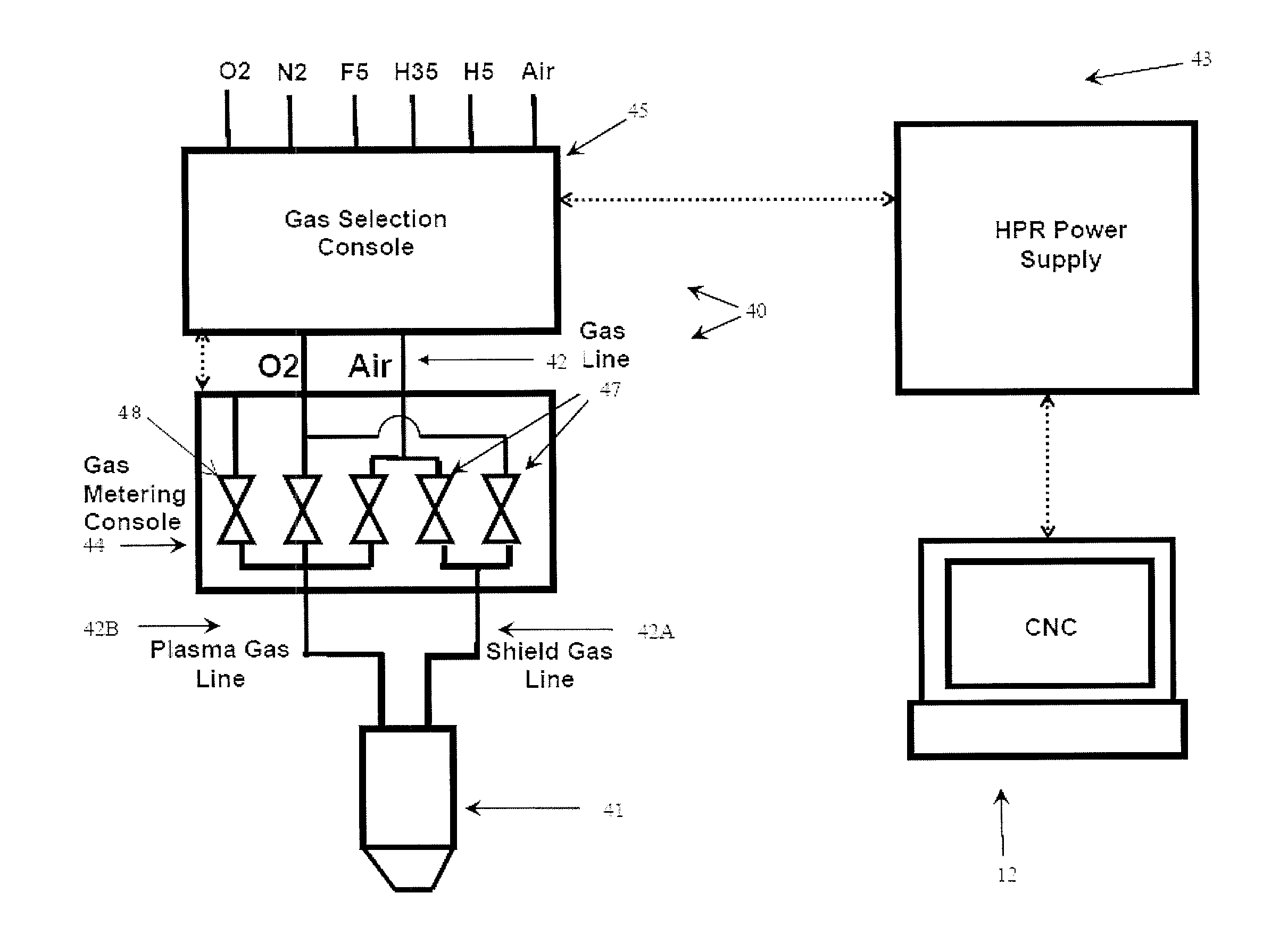
[0010]The present invention substantially improves the cut quality for small internal part features (e.g., hole features) cut from a workpiece using a plasma arc torch while maintaining the productivity and cut quality for large features, or contours. Hole features (e.g., holes) cut using plasma arc torches using known methods can result in defects, such as protrusions (e.g., where not enough material was cut, leaving excess material), divots (e.g., where too much material was cut), bevel and / or taper, which can prevent, for example, a bolt from passing through the bottom of a workpiece. Cutting parameters (e.g., gas composition, cutting speed, cutting current, etc.) can be manipulated to improve the cut quality of a small internal part feature while still maintaining quality for large features or contours. The shield gas composition can affect the taper, or bevel, of the edge of a hole cut that is being performed. For example, a first shield gas composition can be used when cutting the contour, and a second, different, shield gas composition can be used when cutting one or more holes or small internal feature in a single workpiece while using a single plasma torch consumable configuration.
[0011]The cutting speed of the “lead-in” of the cut can affect the cut quality for the hole feature. Using the same speed for the lead-in of the cut as the rest of the cut can result in defects such as protrusions, where the lead of the cut transitions into the perimeter. As noted above, traditionally, an “over burn” process can be used to remove the excess material; however, an over burn process can remove too much material, leaving behind a defect, such as a divot. Using a low N2 gas composition (e.g., a gas composition of O2 plasma gas and O2 shield gas) can also be used to cut small internal features to help minimize the bevel and / or taper. Cutting a workpiece using, for example air, is not as sensitive to defects as cutting with O2 gas. Using O2 plasma and O2 shield gas can further amplify defects such as protrusions and / or divots in the hole feature. By changing the shield gas composition when cutting a hole and when cutting a contour in a single workpiece, the need for secondary processes can be eliminated. While laser cutting systems can yield high quality cuts, plasma arc torch systems provide a low cost alternative to cutting internal features (e.g., hole features).

Problems solved by technology

Hole features (e.g., holes) cut using plasma arc torches using known methods can result in defects, such as protrusions (e.g., where not enough material was cut, leaving excess material), divots (e.g., where too much material was cut), bevel and / or taper, which can prevent, for example, a bolt from passing through the bottom of a workpiece.
Using the same speed for the lead-in of the cut as the rest of the cut can result in defects such as protrusions, where the lead of the cut transitions into the perimeter.
As noted above, traditionally, an “over burn” process can be used to remove the excess material; however, an over burn process can remove too much material, leaving behind a defect, such as a divot.

Method used


Image

  • Method and Apparatus for Cutting High Quality Internal Features and Contours
  • Method and Apparatus for Cutting High Quality Internal Features and Contours
  • Method and Apparatus for Cutting High Quality Internal Features and Contours

Examples


Embodiment Construction

[0102]A “hole feature” (e.g., hole) can be defined as a shape having a diameter (or dimension) to workpiece (plate) thickness ratio of approximately 2.5 or smaller. FIG. 3, by way of example, shows a 6×6 inch square piece of 0.5 inch thick plate steel 100 that in one embodiment, could be cut from a larger workpiece (not shown). A one inch diameter hole feature 105 in the 0.5 inch thick plate of steel 100 would have a ratio of 2. A hole / hole feature, as used herein, can be categorized as a small internal part features that are not necessarily round, but where a majority of the features have dimension that are about 2.5 times or less than the thickness of the materials (e.g., a 1 inch square 110 in the ½ inch plate steel 100). Features such as “contours” can include both straight 115 or curved 120 cuts.

[0103]As noted above, hole features cut using prior art methods can result in defects, such as divots (e.g., too much material taken), protrusions (e.g., not enough material taken), “be...


PUM

PropertyMeasurementUnit
cutting currentaaaaaaaaaa
thickaaaaaaaaaa
diameteraaaaaaaaaa

Abstract

An automated method for cutting a plurality of hole features using a plasma arc torch system can be implemented on a computer numerical controller. The automated method can include the steps of: a) cutting a lead-in for a hole feature using a lead-in command speed based on a diameter of that hole feature and b) cutting a perimeter for the hole feature using a perimeter command speed greater than the corresponding lead-in command speed for the hole feature. The automated method can also include the step c) of repeating steps a) and b) for each additional hole feature having a same diameter or a different diameter.

Description

CROSS-REFERENCE TO RELATED APPLICATION[0001]This application is a continuation application of and claims the benefit of U.S. patent application Ser. No. 12 / 557,920 filed on Sep. 11, 2009, which is a continuation-in-part of U.S. patent application Ser. No. 12 / 466,786 filed on May 15, 2009, and which is also a continuation-in-part of U.S. patent application Ser. No. 12 / 341,731 filed on Dec. 22, 2008, which applications are owned by the assignee of the instant application and the disclosures of which applications are incorporated herein by reference in their entirety. U.S. patent application Ser. No. 12 / 466,786 claims benefit of and priority to U.S. Provisional Patent Application No. 61 / 154,259 filed on Feb. 20, 2009, which is owned by the assignee of the instant application and the disclosure of which is also incorporated herein by reference in its entirety.FIELD OF THE INVENTION[0002]The invention relates generally to plasma arc cutting torch systems. More specifically, the invention...

Claims


Application Information

Patent Timeline
Patent Type & Authority Applications(United States)
IPC IPC(8): B23K10/00
CPCB23K31/10B23K10/00
Inventor LINDSAY, JON W.BEST, GUY T.BRAHAN, PETER V.WILSON, GREGORY S.
Owner HYPERTHERM INC
Learn More