
Intelligent drive control system

Inactive Publication Date: 2012-02-23
DOLLENS DONALD L
View PDF9 Cites 28 Cited by
  • Summary
  • Abstract
  • Description
  • Claims
  • Application Information

AI Technical Summary

Benefits of technology

[0006]The control method and architecture described herein is an improvement over currently available approaches to power application for electric vehicles. It provides a universally applicable method that will improve performance, efficiency, and stability in various forms of vehicle systems as well as other machinery whose purpose is to move material through a manufacturing facility or on the planet's surface. The problem however is that traditional vehicle drive systems do not compensate well under all terrain conditions for the changes in torque demand as the vehicle advances along the surface of the planet or in the manufacturing environment.
[0010]It would also be desirable to provide an improved drive control system that improves delivery of balanced power and speed control to a multi-drive vehicle system and an all-wheel-drive (AWD) electric vehicle. A mathematical model allows the control system to calculate and provide required total power delivery as well as balanced power delivery to each drive within the machine system such that each motor delivers its proportional share of the power needed. Due to the nature of many machine designs, including electric vehicles, it is common to expect that if a number of motors are utilized to share the total work load, there will be times when the work load will be unevenly distributed among drive motors. The present invention overcomes the problem that this uneven power demand imposes.
[0012]Another aspect of the present invention provides a drive control system for a vehicle comprising one or more variable speed and variable torque motors for driving a vehicle. A dynamic force vector calculation program is operable to continuously calculate the torque requirements for each motor in the system. One or more sensors are employed that are operable to create a signal indicative of load conditions and, if required, additional data including the weight of such load or loads, slippage of the wheels, and terrain characteristics, and then send data to a computer. The computer is operable to process the signals from the sensors using the dynamic force vector calculation program and in turn generates real time drive torque data for each motor. A variable drive controller is operable to control each variable speed motor within the system so that proper torque is generated by each motor as is required for optimum performance. The resulting intelligent drive control system is dynamic and continuously monitors torque requirements for each motor within the vehicle system given current load data and environmental conditions so as to maximize operating efficiency of the vehicle.

Problems solved by technology

However, such drive systems have inefficiencies, are complex, and traditionally do not account for environmental conditions while selectively controlling in real time each drive wheel.
The problem however is that traditional vehicle drive systems do not compensate well under all terrain conditions for the changes in torque demand as the vehicle advances along the surface of the planet or in the manufacturing environment.

Method used


Image

  • Intelligent drive control system
  • Intelligent drive control system
  • Intelligent drive control system

Examples


Embodiment Construction

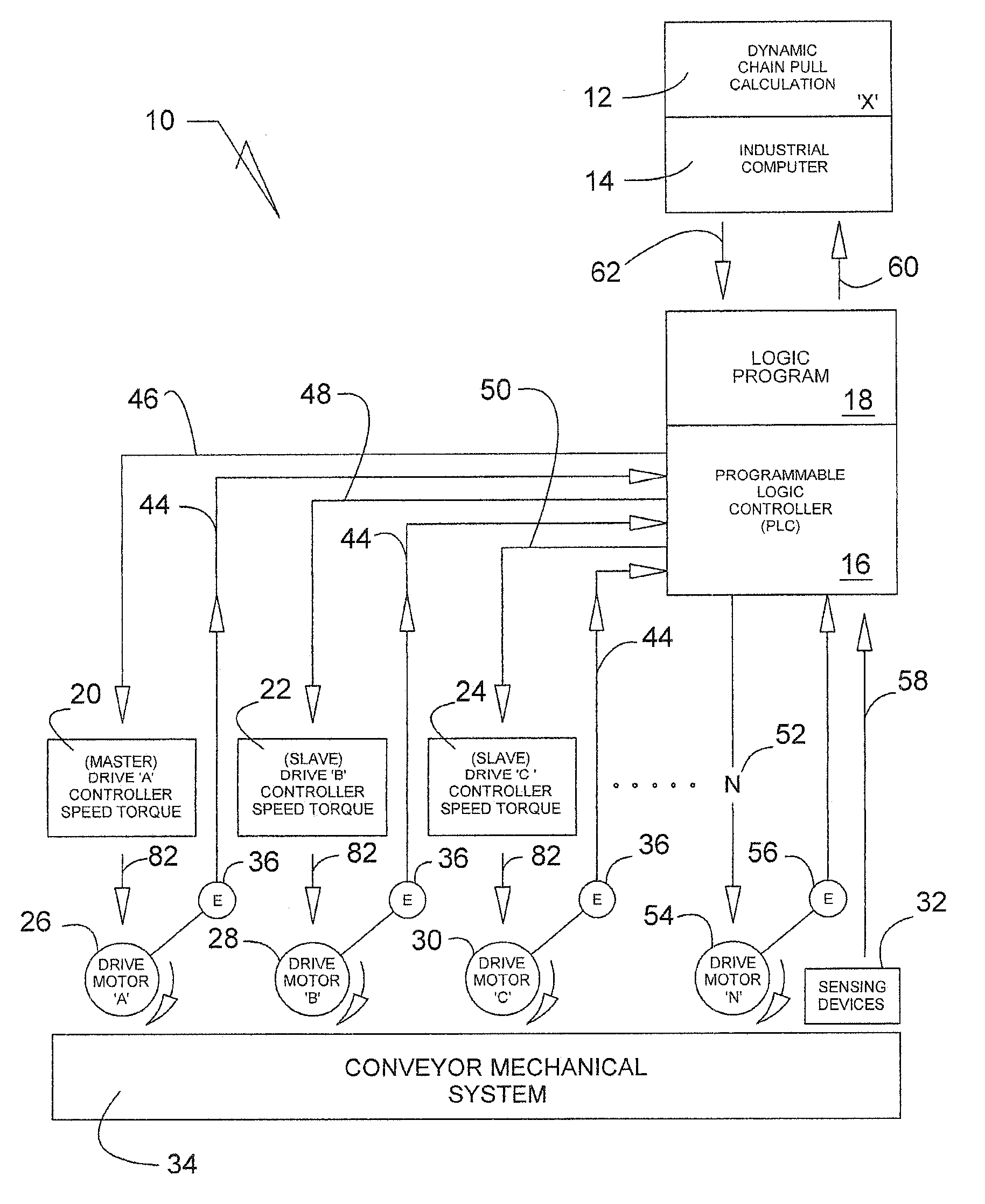
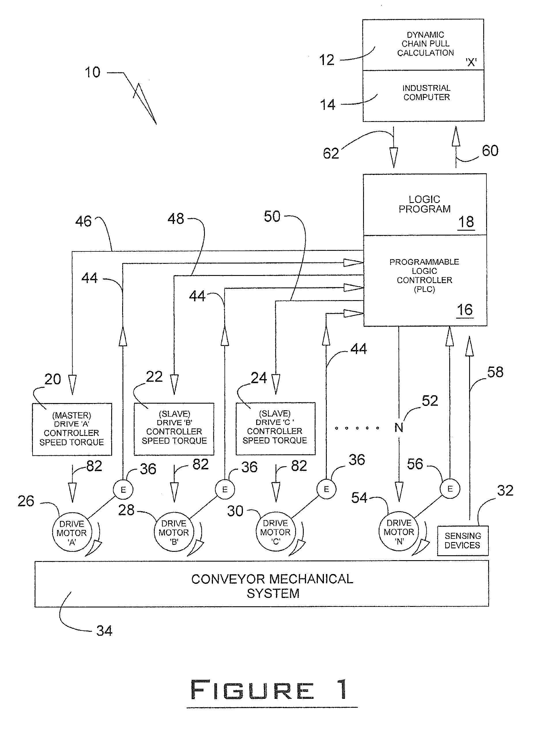
[0020]A drive control system 10 is illustrated in FIG. 1 and includes a dynamic chain pull calculation computer software program 12, and industrial computer 14, a PLC 16 with software 18, a plurality of drive controllers 20, 22 and 24, a plurality of drive motors 26, 28 and 30 and sensing devices 32. The drive control system 10 is integrated with a conveyor 34 which includes typical components for moving work pieces throughout an assembly line. It will be appreciated that the present drive control system 10 can be utilized wherever it is desired to dynamically control the movement of material from place to place.

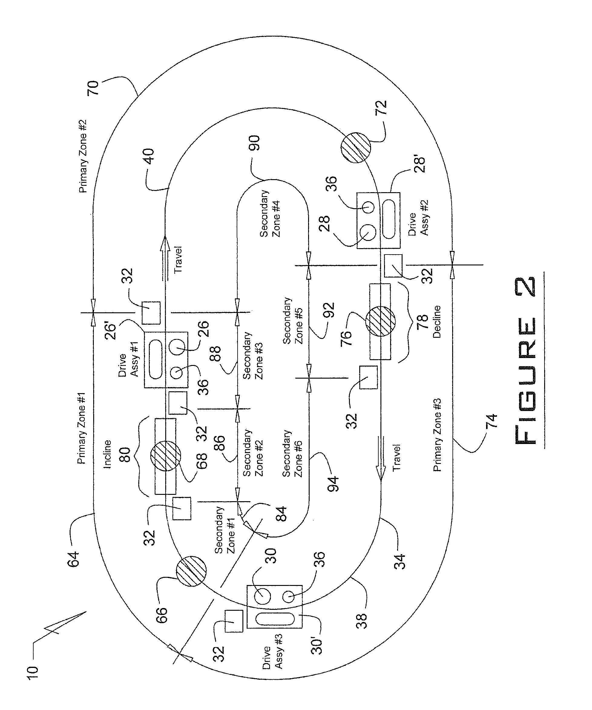
[0021]With continued reference to FIG. 1, an individual encoder 36 is placed in proximity to drive motors 26, 28 and 30 for counting and monitoring the links 38 that comprise a conveyor or chain 40. The conveyor chain can be in excess of the 2,000 ft. limitation that is typically ascribed to chain conveyor applications. Through utilization of the encoders 36, the specific nu...


PUM


Abstract

A drive control system for a moving device such as a vehicle uses a dynamic force vector program that is hosted by a computer on the vehicle. Variable controllers receive input from the computer that automatically adjusts drive and slave motors which in turn propel an associated drive member so as to maximize efficiency of the operation of the vehicle in various terrain conditions. Sensing devices provide continuous load and condition parameters to the computer that in turn adjusts the torque outputs for the variable controllers which in turn dynamically adjusts the vehicle's operation based on current operating conditions.

Description

CROSS REFERENCES TO RELATED APPLICATIONS[0001]This application is a continuation-in-part of U.S. patent application Ser. No. 11 / 725,662 filed on Mar. 20, 2007, and hereby incorporates such application in its entirety by reference.FIELD OF THE INVENTION[0002]A drive control system for use in connection with a vehicle, more specifically, an intelligent dynamic vehicle drive control system that employs a mathematical model to effectuate delivery of balanced power and speed control for a vehicle so as to maximize efficiency of the vehicle on the surface of a planet.BACKGROUND AND SUMMARY OF THE INVENTION[0003]It is well known to provide an electric vehicle that is powered by one or more electric motors to move the vehicle from place to place. In many instances, single electric drive motors are utilized to provide primary power which is delivered to the driven wheels by a series of mechanical devices including transmissions, differentials, drive shafts, and other components that have bee...

Claims


Application Information

Patent Timeline
IPC IPC(8): B60L15/20
CPCB60K7/0007B60K17/356B60W30/18B60W30/18172B60W2300/18B60W2520/26Y02T10/7258B60W2520/406B60Y2200/24B60Y2200/46G05B2219/41112G05B2219/45054B60W2520/403Y02T10/72
Inventor DOLLENS, DONALD L.
Owner DOLLENS DONALD L
Learn More