
Image pickup system, camera and interchangeable lens

Inactive Publication Date: 2012-02-23
CANON KK
View PDF9 Cites 11 Cited by
  • Summary
  • Abstract
  • Description
  • Claims
  • Application Information

AI Technical Summary

Benefits of technology

[0008]The present invention provides as one aspect thereof an image pickup system including a camera and an interchangeable lens to be detachably attached to the camera. The interchangeable lens has an image-taking optical system that includes a magnification-varying lens being moved in an optical axis direction to perform variation of magnification and a compensating lens being moved in the optical axis direction to reduce focus variation caused due to the variation of magnification. The camera includes an image sensor configured to photoelectrically convert an object image formed by the image-taking optical system, an image sensor driver configured to move the image sensor in the optical axis direction, and a camera controller configured to control movement of the image sensor through the image sensor driver such that the focus variation caused due to the variation of magnification of the image-taking optical system is reduced. The camera controller is configured to acquire image sensor moving data corresponding to the interchangeable lens attached to the camera, and controls the movement of the image sensor by using the image sensor moving data.
[0009]The present invention provides as another aspect thereof a camera to which an interchangeable lens is detachably attached, the interchangeable lens having an image-taking optical system that includes a magnification-varying lens being moved in an optical axis direction to perform variation of magnification and a compensating lens being moved in the optical axis direction to reduce focus variation caused due to the variation of magnification. The camera includes an image sensor configured to photoelectrically convert an object image formed by the image-taking optical system, an image sensor driver configured to move the image sensor in the optical axis direction, and a camera controller configured to control movement of the image sensor through the image sensor driver such that the focus variation caused due to the variation of magnification of the image-taking optical system is reduced. The camera controller is configured to acquire image sensor moving data corresponding to the interchangeable lens attached to the camera, and controls the movement of the image sensor by using the image sensor moving data.
[0010]The present invention provides as still another aspect thereof an interchangeable lens to be detachably attached to a camera. The interchangeable lens includes an image-taking optical system including a magnification-varying lens being moved in an optical axis direction to perform variation of magnification and a compensating lens being moved in the optical axis direction to reduce focus variation caused due to the variation of magnification. The camera includes an image sensor configured to photoelectrically convert an object image formed by the image-taking optical system, an image sensor driver configured to move the image sensor in the optical axis direction, and a camera controller configured to control movement of the image sensor through the image sensor driver such that the focus variation caused due to the variation of magnification of the image-taking optical system is reduced by using image sensor moving data corresponding to the interchangeable lens attached to the camera. The interchangeable lens sends, in response to a requirement from the camera controller, the image sensor moving data corresponding to the interchangeable lens to the camera controller.

Problems solved by technology

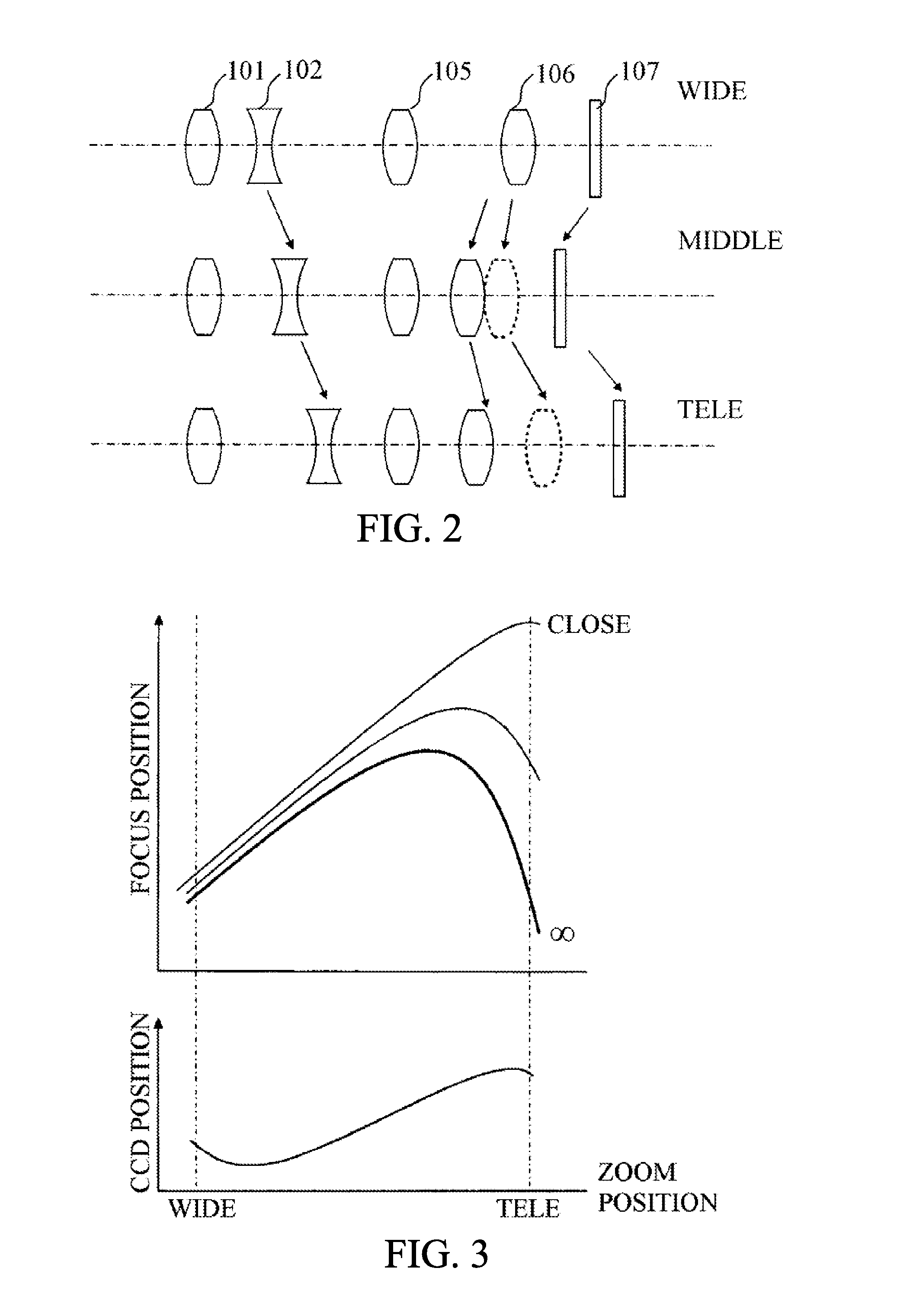
The problem is that, in a case where the camera performs the movement control of the image sensor according to the variation of magnification in the interchangeable lens, the camera should perform appropriate movement control of the image sensor according to an optical configuration and an optical characteristic of the interchangeable lens.
Inappropriate movement control of the image sensor makes it impossible to obtain a good zoom tracking result.

Method used


Image

  • Image pickup system, camera and interchangeable lens
  • Image pickup system, camera and interchangeable lens
  • Image pickup system, camera and interchangeable lens

Examples


Embodiment Construction

[0019]Exemplary embodiments of the present invention will hereinafter be described with reference to the accompanying drawings.

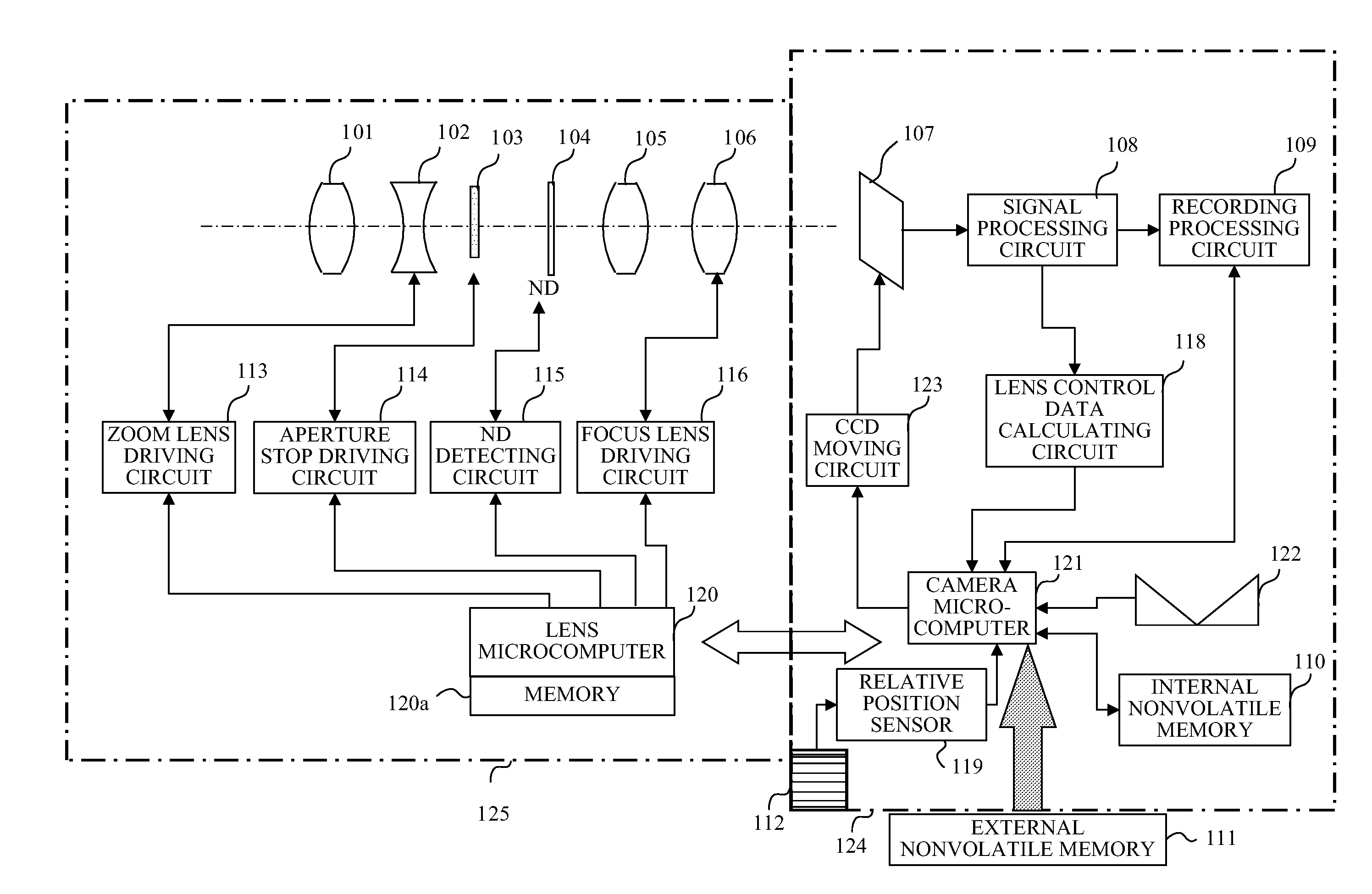
[0020]FIG. 1 shows the configuration of a lens-interchangeable image pickup system that is an embodiment of the present invention. The image pickup system is constituted by an image pickup unit (hereinafter referred to as a “camera”) 124 and an interchangeable lens unit 125 interchangeable with respect to (detachably attached to) the camera 124. The interchangeable lens unit 125 is one of interchangeable lens units having mutually different optical configurations and mutually different optical characteristics.

[0021]Light from an object (not shown) enters an image-taking optical system in the interchangeable lens unit 125. The image-taking optical system includes, in order from an object side, a fixed front lens 101, a magnification-varying lens 102 that is moved in an optical axis direction to perform variation of magnification, an aperture stop 103 that adj...


PUM


Abstract

The image pickup system includes a camera and an interchangeable lens having an image-taking optical system. The camera includes an image sensor to photoelectrically convert an object image formed by the image-taking optical system and to be moved in an optical axis direction, and a camera controller configured to control movement of the image sensor such that focus variation caused due to variation of magnification of the interchangeable lens is reduced. The camera controller is configured to acquire image sensor moving data corresponding to the interchangeable lens attached to the camera, and controls the movement of the image sensor by using the image sensor moving data.

Description

BACKGROUND OF THE INVENTION[0001]1. Field of the Invention[0002]The present invention relates to an image pickup system capable of performing zoom tracking control by moving an image sensor, particularly to a lens-interchangeable image pickup system.[0003]2. Description of the Related Art[0004]Image-taking optical systems, which are capable of performing variation of magnification by moving a magnification-varying lens and in which the variation of magnification causes image plane variation, move a compensating lens (for example, a focus lens) other than the magnification-varying lens in an optical axis direction so as to compensate for the image plane variation to maintain an in-focus state. Control of such movement of the compensating lens for compensating for the image plane variation caused due to the variation of magnification is referred to as “zoom tracking (or zoom tracking control)”.[0005]Japanese Patent Laid-Open No. 63-087871 discloses a camera that moves, in addition to ...

Claims


Application Information

Patent Timeline
IPC IPC(8): G03B13/32
CPCG03B3/10G03B17/14G03B13/34
Inventor UCHIYAMA, MINORU
Owner CANON KK
Learn More