System for vehicle braking detection

Active Publication Date: 2012-02-23
HARMAN BECKER AUTOMOTIVE SYST
View PDF12 Cites 133 Cited by
  • Summary
  • Abstract
  • Description
  • Claims
  • Application Information

AI Technical Summary

Benefits of technology

[0010]With this method it is possible to automatically obtain an indication of the braking strength (or braking deceleration) of the second vehicle travelling ahead. Since the information is automatically obtained, reaction time may be reduced. As an example, the driver of the first vehicle may be warned if the second (preceding) vehicle is braking hard (decelerating quickly), or braking lightly (decelerating more slowly). In addition, for example, an automated driver assistance system may be automatically engaged on the basis of the derived information. Since reaction times can be reduced, the braking of the first vehicle can be initialized earlier and rear end collisions with the second (preceding) vehicle may be avoided.
[0013]When evaluating a detected optical signal, at least one of the following information on the braking procedure performed by the second (or preceding) vehicle may be derived: An emergency braking performed by the second vehicle, a rate of deceleration of the second vehicle, an activation of an anti-lock braking system, or the locking of a wheel of the second vehicle. Obtaining such information has the advantage that a warning tailored to the actual traffic situation can be provided to the driver or an automated driver assistance system can be enabled or provided in accordance with the current traffic situation.
[0027]With such a lighting control unit, information on the braking procedure performed by the vehicle into which the unit is installed can be relayed to a following vehicle. The vehicle lighting control unit may thus interact with the system described previously if such a system is installed in the following vehicle. The device may automatically detect and decode the information transmitted by the vehicle lighting control unit. If the vehicle performs severe braking, the reaction time of following vehicles can be reduced, and rear end collisions may thus be prevented.
[0031]The system for vehicle brake detection may improve warning of a driver so that rear end collisions can be avoided. In particular, the reaction time after which a following vehicle starts to decelerate may be improved. Also, the following vehicle can benefit from having more information available on the braking procedure being performed by the preceding vehicle.

Problems solved by technology

Conventional vehicles are equipped with brake lights which are illuminated in response to the driver actuating the brake pedal of the vehicle, resulting in a deceleration of the vehicle.
This can be problematic for a driver in a following vehicle who only observes the illumination of the brake lights but has no indication about how strong the preceding vehicle is braking.
Yet such systems have not been able to show a significant improvement in the prevention of rear end collisions.
Yet some signals, such as a relative intensity between different light emitting areas or an intensity change of emitted light may not be human-perceivable.

Method used


Image

  • System for vehicle braking detection
  • System for vehicle braking detection
  • System for vehicle braking detection

Examples


Embodiment Construction

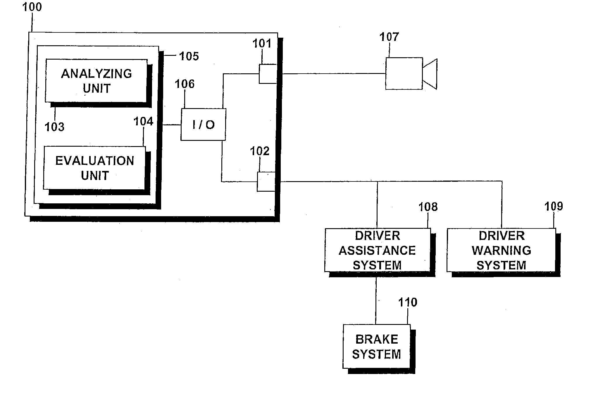
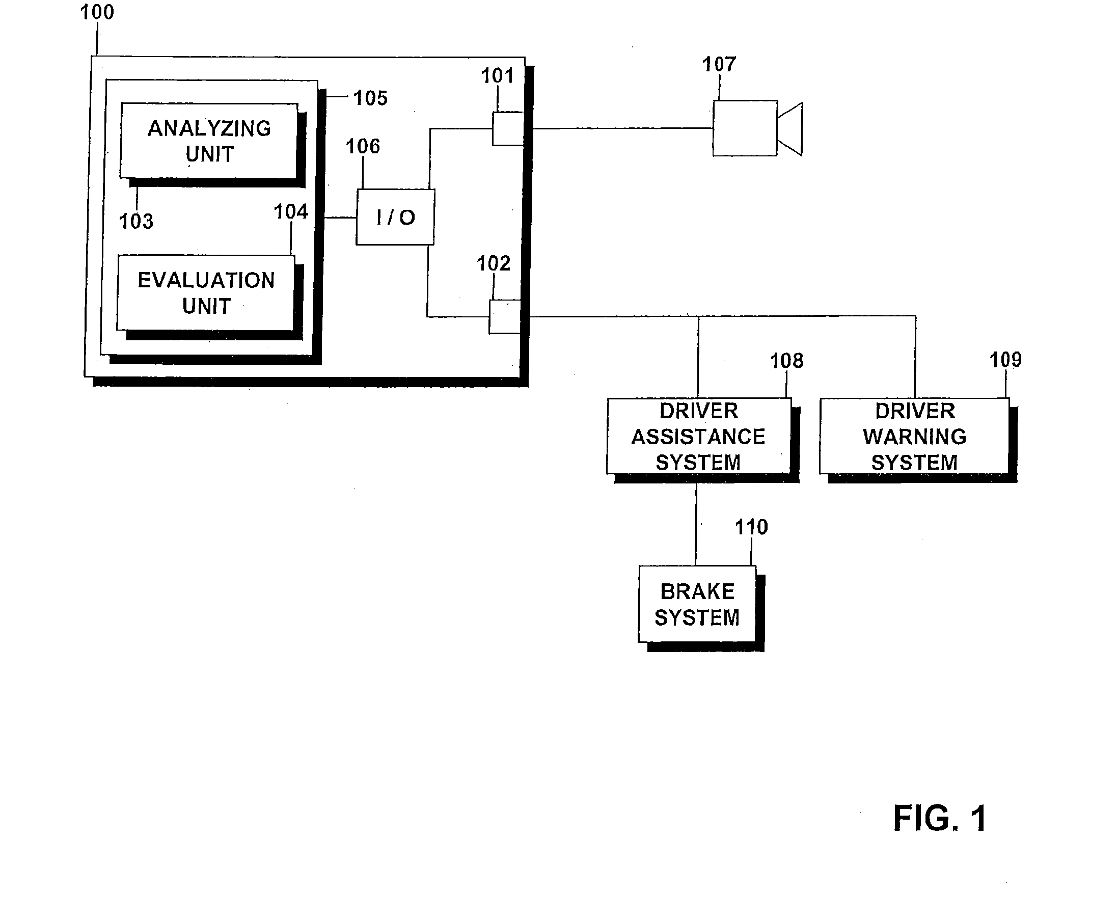
[0040]FIG. 1 schematically illustrates the components of an example system for vehicle braking detection that includes a device 100 for detecting braking of a vehicle. The device 100 is mounted to a vehicle which may be equipped with a driver assistance system 108. Device 100 may be part of the driver assistance system 108, yet it may also be independent of the driver assistance system 108. In other examples, the driver assistance system 108 may be omitted. Device 100 includes an interface 101 in communication with a detector 107.

[0041]Detector 107 is mounted to the vehicle such that it detects light coming from a region in front of the vehicle. Detector 107 can thus detect light which is emitted by a light source, such as the rear lights of a vehicle travelling in front of the vehicle upon which device 100 is mounted. Detector 100 can for example detect light emitted by light sources such as brake lights, hazard flashers, tail lights and the like. Several implementations of detecto...


PUM


Abstract

A system for detection of braking of a vehicle may include a device provided in a first vehicle. The device may be in communication with a detector mounted to the first vehicle to monitor an area in front of the first vehicle. The detector may detect light emitted by the rear lights of a second vehicle when the second vehicle is ahead of the first vehicle in the monitored area. The device may acquire data from the detector and analyze the acquired data in order to detect an optical signal emitted by the rear lights of the second vehicle. The optical signal may encode information indicative of a braking procedure being performed by the second vehicle. The device may evaluate the detected optical signal in order to derive the information indicative of the braking procedure of the second vehicle.

Description

BACKGROUND OF THE INVENTIONPriority Claim[0001]This application claims the benefit of priority from European Patent Application No. EP 10 008 769.1, filed Aug. 23, 2010, which is incorporated by reference.[0002]1. Technical Field[0003]The invention relates to a system for detecting braking of a vehicle based on light emitted from rear lights of the vehicle. The invention further relates to a vehicle lighting control unit which controls the emission of light from rear lights of a vehicle.[0004]2. Related Art[0005]Conventional vehicles are equipped with brake lights which are illuminated in response to the driver actuating the brake pedal of the vehicle, resulting in a deceleration of the vehicle. The driver of a following vehicle is thus warned and enabled to react by reducing speed. Modern vehicles often have an improved braking performance which can for example be achieved by making use of electronic systems such as the anti-lock braking system (ABS) or an electronic stability cont...

Claims


Application Information

Patent Timeline
IPC IPC(8): B60Q1/44
CPCB60T7/22G08G1/161B60T17/22B60Q1/44
Inventor MAUDERER, HANS-PETERHUBNER, KLAUS
Owner HARMAN BECKER AUTOMOTIVE SYST
Why Eureka
Try Eureka