Eureka AIR delivers breakthrough ideas for toughest innovation challenges, trusted by R&D personnel around the world.

Semiconductor device and electronic apparatus including the same

a technology of semiconductor devices and electronic devices, applied in the direction of semiconductor devices, semiconductor/solid-state device details, electrical devices, etc., can solve the problem of excessive through-hole making process, and achieve the effect of reducing the variation in the connection area

Inactive Publication Date: 2012-02-23
PANASONIC CORP
View PDF1 Cites 2 Cited by
  • Summary
  • Abstract
  • Description
  • Claims
  • Application Information

AI Technical Summary

Benefits of technology

"The present invention provides a semiconductor device with stable formation of through electrodes for different wiring layers. By using an adjustment layer between the semiconductor substrate and the wiring layers, the thickness of the adjustment layer is reduced, resulting in a reduction in processing time for forming the through electrodes. This ensures that the through electrodes are formed stably without causing electrical conduction disorder or reduced reliability. The semiconductor device also includes insulating layers that correspond one-to-one to the wiring layers, further reducing the likelihood of hollowing or breakage. Overall, the present invention provides a solution for preventing the conventional problems associated with through electrodes in solid-state imaging devices."

Problems solved by technology

(iii) Through-hole making process is excessively performed for a lowermost layer electrode portion (an electrode portion which the through electrode is first in contact with).

Method used


Image

  • Semiconductor device and electronic apparatus including the same
  • Semiconductor device and electronic apparatus including the same
  • Semiconductor device and electronic apparatus including the same

Examples


embodiment 1

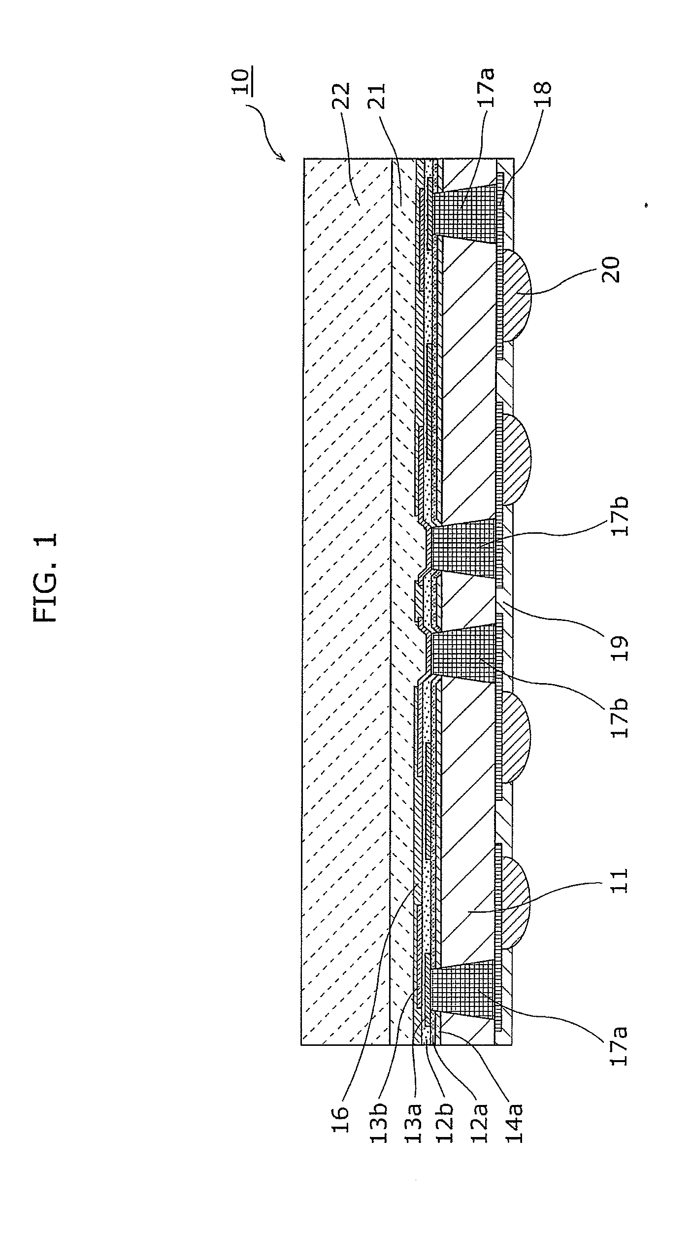
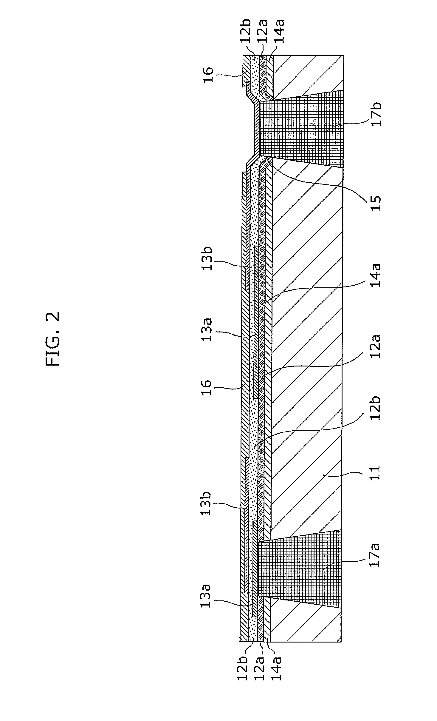
[0066]A semiconductor device according to Embodiment 1 includes: a semiconductor substrate having metal wiring formed on a bottom surface of the semiconductor substrate; and a plurality of wiring layers formed above the semiconductor substrate. The wiring layers include a first wiring layer and a second wiring layer that is formed above the first wiring layer. The semiconductor device further includes: a first through electrode which electrically connects the first wiring layer and the metal wiring; a second through electrode which electrically connects the second wiring layer and the metal wiring; and at least one adjustment layer formed between the semiconductor substrate and the wiring layers. The at least one adjustment layer includes a first adjustment layer formed on a region excluding a region corresponding to the second through electrode.

[0067]Following describes a configuration of the semiconductor device according to Embodiment 1 of the present invention with reference to ...

embodiment 2

[0096]A semiconductor device according to Embodiment 2 is substantially the same as the semiconductor device 10 according to Embodiment 1 but is different in that the layer difference adjustment film is made of a different material than that of the second insulating film 12b. Following describes a configuration of the semiconductor device according to Embodiment 2 of the present invention with reference to FIG. 3.

[0097]FIG. 3 is a cross-sectional view showing part of a configuration of the semiconductor device according to this embodiment.

[0098]The semiconductor device according to Embodiment 2 shown in FIG. 3 includes, instead of the layer difference adjustment film 14a in Embodiment 1 shown in FIG. 2, a layer difference adjustment film 14b. The layer difference adjustment film 14b is thin compared to the thickness of the layer difference adjustment film 14a. Furthermore, the layer difference adjustment film 14b is made of a different material than that of the second insulating fil...

embodiment 3

[0099]A semiconductor device according to Embodiment 3 is different from the semiconductor device 10 according to Embodiment 1 in that the wiring layers further include a third wiring layer formed between the first wiring layer and the second wiring layer, the semiconductor device further includes a third through electrode which electrically connects the third wiring layer and the metal wiring, and the at least one adjustment layer further includes a second adjustment layer formed on a region excluding a region corresponding to the second through electrode and a region corresponding to the third through electrode.

[0100]Following describes a configuration of the semiconductor device according to Embodiment 3 of the present invention with reference to FIG. 4.

[0101]FIG. 4 is a cross-sectional view showing part of a configuration of the semiconductor device according to this embodiment.

[0102]Compared to the semiconductor device 10 shown in FIG. 2, the semiconductor device according to E...


PUM


Abstract

A semiconductor device according to the present invention is a semiconductor device that includes: a semiconductor substrate having metal wiring formed on a bottom surface of the semiconductor substrate; and a plurality of wiring layers formed above the semiconductor substrate. The wiring layers include a first wiring layer and a second wiring layer that is formed above the first wiring layer. The semiconductor device further includes: a first through electrode which electrically connects the first wiring layer and the metal wiring; a second through electrode which electrically connects the second wiring layer and the metal wiring; and at least one layer difference adjustment film formed between the semiconductor substrate and the wiring layers. The at least one layer difference adjustment film includes a layer difference adjustment film formed on a region excluding a region corresponding to the second through electrode.

Description

CROSS REFERENCE TO RELATED APPLICATION [0001]This is a continuation application of PCT application No. PCT / JP2010 / 000855 filed on Feb. 12, 2010, designating the United States of America.BACKGROUND OF THE INVENTION [0002](1) Field of the Invention[0003]The present invention relates to semiconductor devices.[0004](2) Description of the Related Art[0005]In order to reduce the size, thickness, and weight of electronic apparatuses and achieve packaging thereof in a high density, many semiconductor devices manufactured using techniques of wafer-level chip size packaging (CSP) which enables fabrication processing at wafer level, have been used in recent electronic apparatus.[0006]An example of the application of such semiconductor device includes solid-state imaging devices which are typical of optical devices. The solid-state imaging devices are used as photosensors in digital imaging apparatuses, such as digital still cameras, cameras built in mobile phones, and digital camcorders. In or...

Claims


Application Information

Patent Timeline
Patent Type & Authority Applications(United States)
IPC IPC(8): H01L23/48
CPCH01L23/3114H01L2924/00014H01L23/525H01L27/14618H01L31/022408H01L2224/02372H01L2224/05548H01L2224/05567H01L2224/13022H01L2224/13024H01L23/481H01L2224/0401H01L2224/131H01L2924/0002H01L2224/1132H01L2924/014H01L2224/05552
Inventor NAKANO, TAKAHIRO
Owner PANASONIC CORP
Why Eureka
Eureka Blog
Learn More