
Grinding system

a grinding system and grinding surface technology, applied in the field of grinding system, can solve the problems of poor grinding, misalignment of grinding surfaces, and possible misalignment of pestle shafts, and achieve the effects of less complex sealing arrangement, less expensive, and less grinding

Active Publication Date: 2012-02-23
BIOMEDICAL POLYMERS
View PDF0 Cites 24 Cited by
  • Summary
  • Abstract
  • Description
  • Claims
  • Application Information

AI Technical Summary

Benefits of technology

[0004]It is a further object of this invention to provide such an improved grinding system with improved grinding performance.
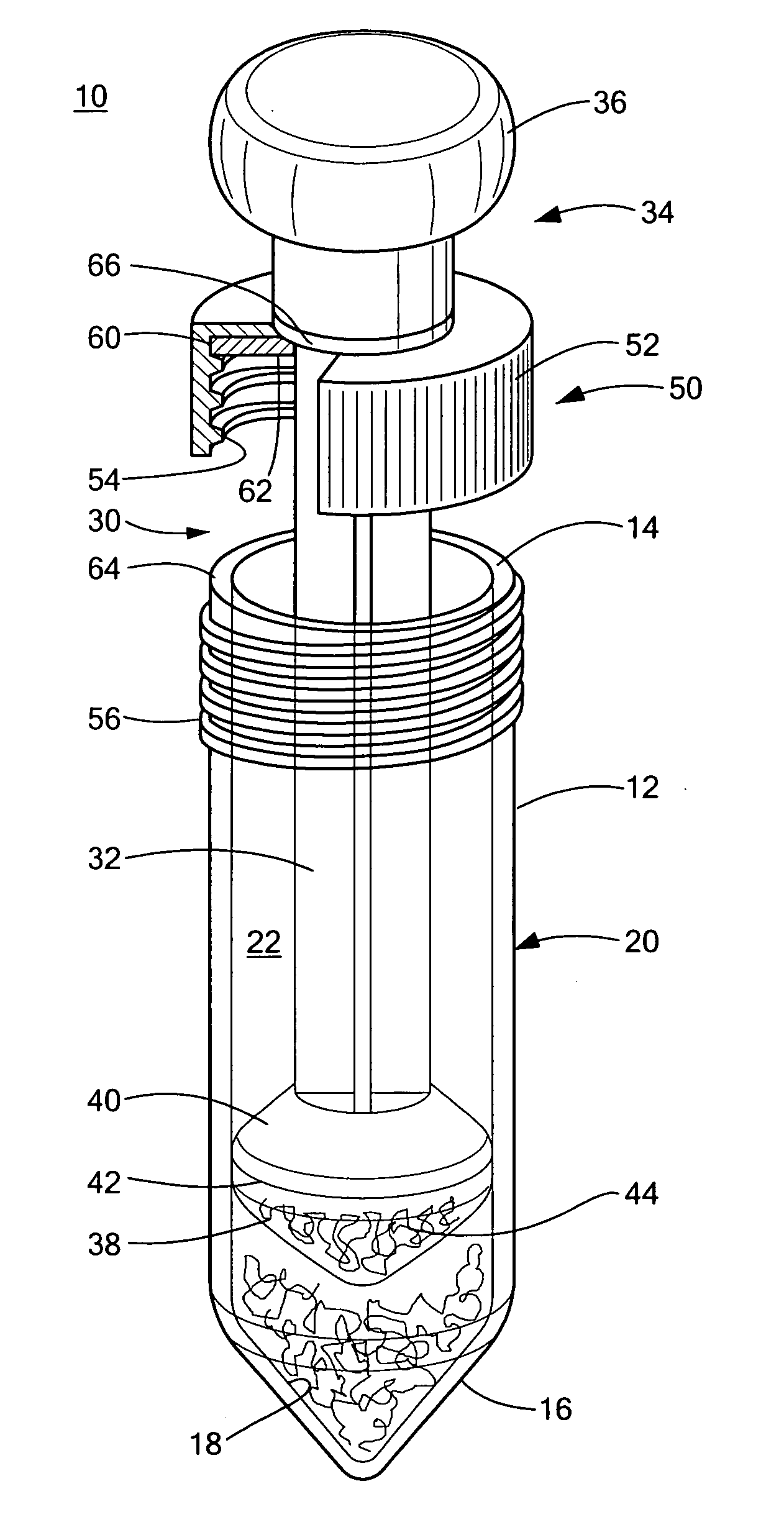
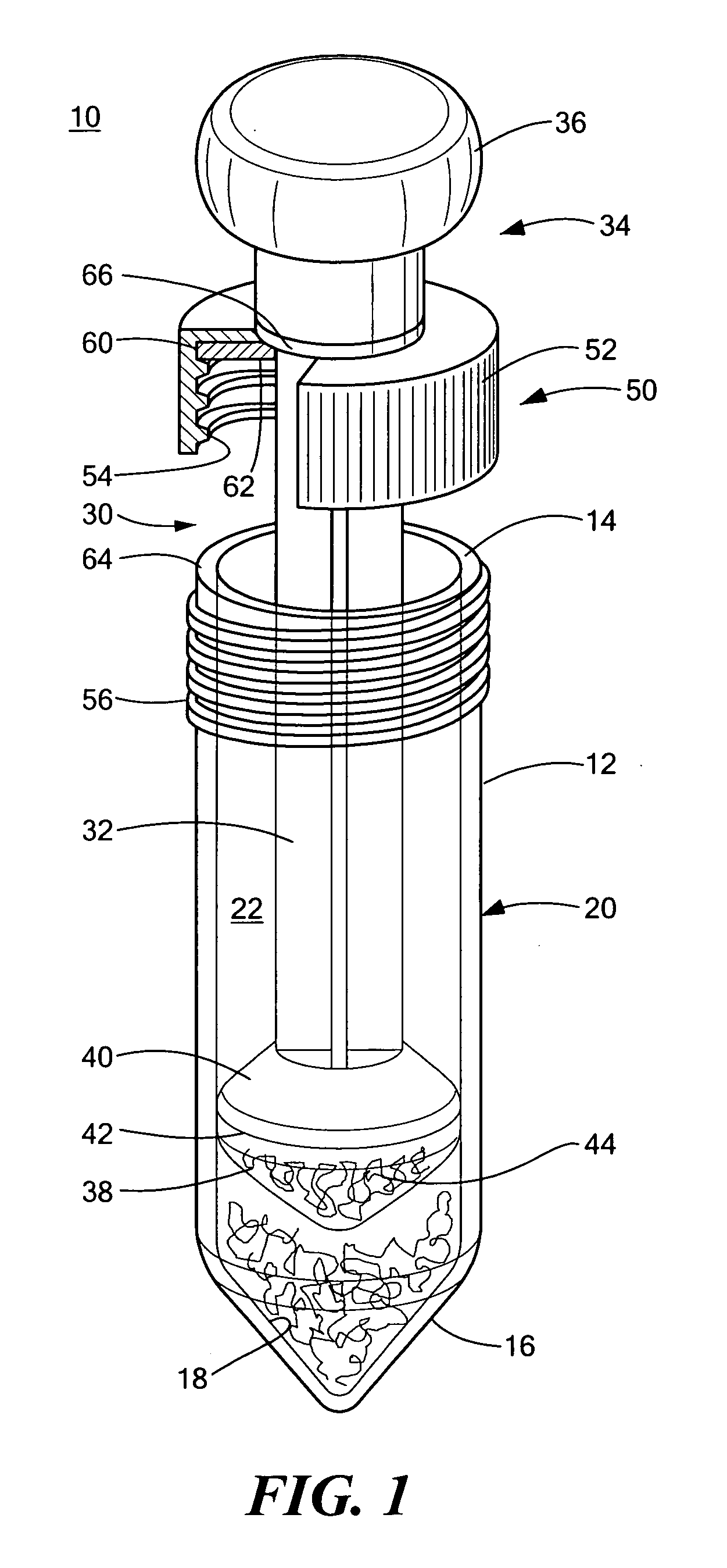
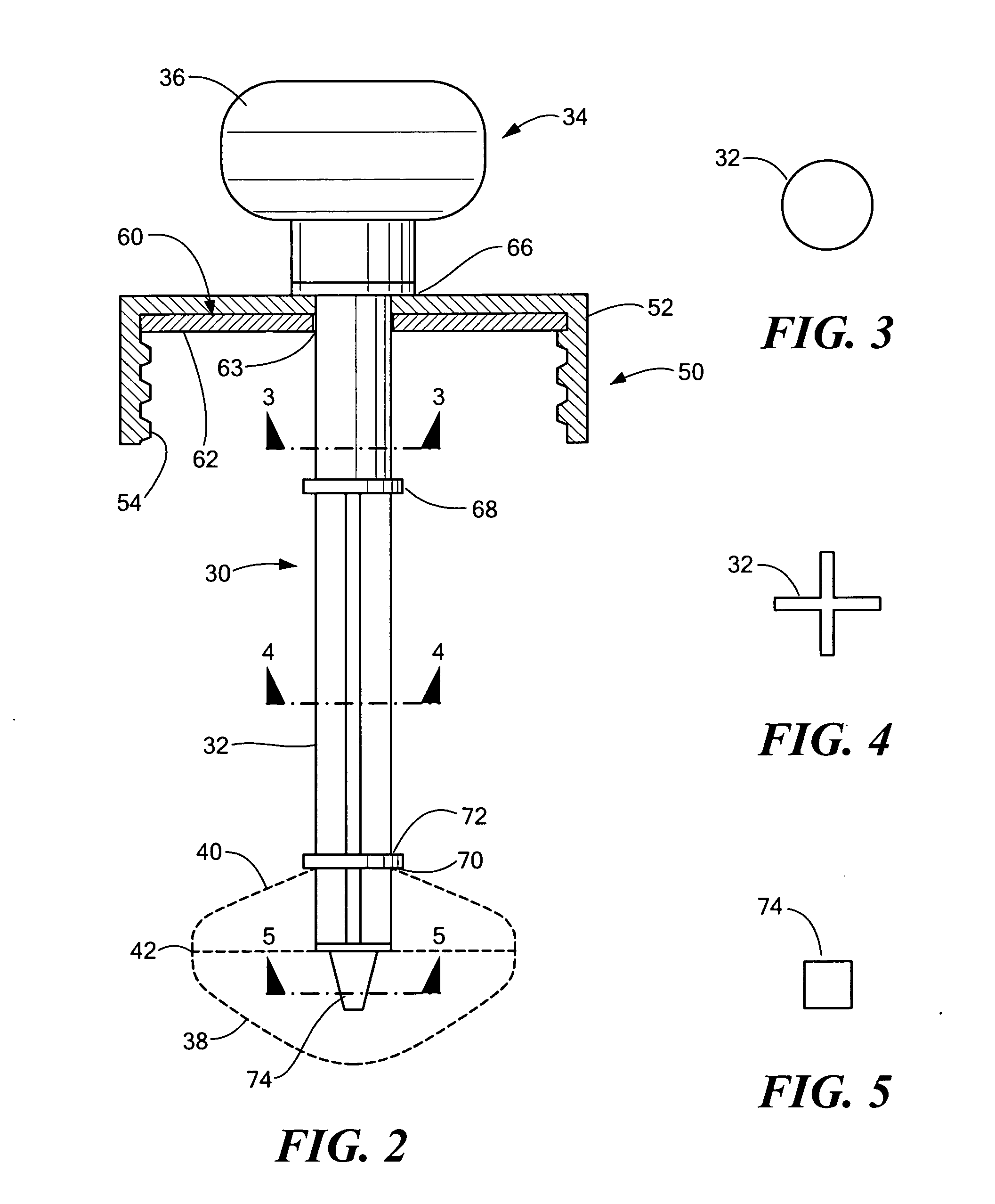
[0011]The invention results from the realization that an improved, modular grinding system which is simpler, easier and less expensive can be achieved using a modular pestle assembly including a universal pestle shaft having at its proximate end an actuator portion extending above the top portion of the container and at its distal end a mounting portion for receiving sets of pairs of matching pestle tips and pestle collars. A closure device sealingly engages with the pestle assembly and the top of the container to define a collection chamber.

Problems solved by technology

Often the pestle is made in two or more parts which requires an assembly step and more importantly introduces the opportunity for misalignment of the pestle shaft during assembly.
This can result in misalignment of the grinding surfaces and poor grinding results.
Another issue is the complexity of the sealing of the cap with the container.
A further issue arises because a number of different sizes are needed.
Another problem encountered when the pestle tip is made of one solid piece is “sinking”.
Sinking is the dimpling or concavity which occurs in thick molded parts where cooling causes shrinkage resulting in surface sinking.

Method used


Image

  • Grinding system
  • Grinding system
  • Grinding system

Examples


Embodiment Construction

[0033]Aside from the preferred embodiment or embodiments disclosed below, this invention is capable of other embodiments and of being practiced or being carried out in various ways. Thus, it is to be understood that the invention is not limited in its application to the details of construction and the arrangements of components set forth in the following description or illustrated in the drawings. If only one embodiment is described herein, the claims hereof are not to be limited to that embodiment. Moreover, the claims hereof are not to be read restrictively unless there is clear and convincing evidence manifesting a certain exclusion, restriction, or disclaimer.

[0034]The grinding system of this invention may be used in a number of different applications such as plant research, mineral research, pharmaceutical research, (e.g. tablets), wood pulp, animal research and with human tissue, bone and cartilage. One of the more likely uses is for tissue grinding and the embodiment describe...


PUM


Abstract

A grinding system includes a mortar container having an open top portion and a bottom portion having a first interior grinding surface and a wall portion interconnecting the top and bottom portions for defining a hollow interior collection chamber, a modular pestle assembly including a universal pestle shaft having at its proximate end an actuator portion extending above the top portion and at its distal end a mounting portion for receiving one of a set of pairs of matching tips and pestle collars, the pestle tip having a second grinding surface for engaging the first grinding surface, and a closure device sealingly engageable with the pestle assembly and the open top portion for sealing the container and the collection chamber between the grinding surfaces and the top portion of the mortar container.

Description

FIELD OF THE INVENTION[0001]This invention relates to a grinding system and more particularly to such a system with a modular pestle assembly for receiving a number of different pestle tips and collars with use in multiple tube configurations for a variety of applications, i.e. research, clinical, industrial.BACKGROUND OF THE INVENTION[0002]Grinders are widely used to grind up small quantities of material for further processing and analysis. A container acting as a mortar has a grinding surface in the interior of its base usually conical or rounded in shape for receiving the grinding material. A pestle which is received in the container has a similarly shaped grinding surface and a cap is sealing engaged with the pestle shaft and the top of the container. Often the pestle is made in two or more parts which requires an assembly step and more importantly introduces the opportunity for misalignment of the pestle shaft during assembly. This can result in misalignment of the grinding sur...

Claims


Application Information

Patent Timeline
Patent Type & Authority Applications(United States)
IPC IPC(8): B02C19/08
CPCB02C19/08
Inventor FAULKER, MICHAEL
Owner BIOMEDICAL POLYMERS
Learn More