
Wave energy turbine for oscillating water column systems

a technology of wave energy turbine and oscillating water column, which is applied in the direction of electric generator control, couplings, fluid couplings, etc., can solve the problems of unique challenges of oscillating water column systems, performance and efficiency issues, and the design of wells continues to be challenged, and achieves simple and robust effects

Active Publication Date: 2012-02-16
INYANGA TECH LTD
View PDF6 Cites 14 Cited by
  • Summary
  • Abstract
  • Description
  • Claims
  • Application Information

AI Technical Summary

Benefits of technology

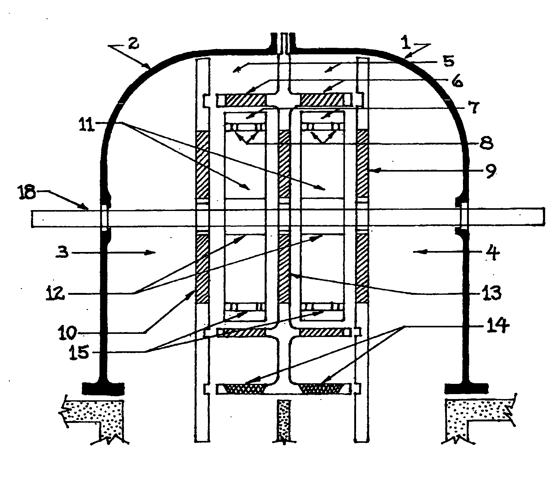
[0009]The object of the present invention is to provide a simple and robust uni-directional turbine design for use in reciprocating air flow environments. The size is scalable between four and nine feet in diameter, thus it can be configured to the job at hand. The device has two rotors with asymmetrical airfoils (11) that are coupled to a common shaft (18) by means of free-wheel (Sprag-type) clutches (12) located at the center of each of the rotor hubs. Both of the rotor assemblies are made up of an even number of hollow airfoil blades (11). The leading edges of the radial blades are oriented at an optimal angle of attack to the oncoming axial air stream.
[0010]Since the air stream will reverse during a complete wave cycle, each rotor set is a mirror image of the other. Depending on the direction of air flow, the air will impinge upon the leading edges of one rotor set while passing on to the trailing edges of the blades in the other rotor set. The trailing edges of the downstream rotor blades are configured to produce some lift and will assist in maintaining directional momentum.
[0011]The Sprag-type clutch (12) in each of the hubs allows the upstream (drive) rotor to turn the shared axle shaft (18), while the other downstream (passive) rotor is in a free-wheeling condition exerting little frictional loss to the common axle (18). Thus, the axle will rotate at all times in one direction, regardless of air flow direction.
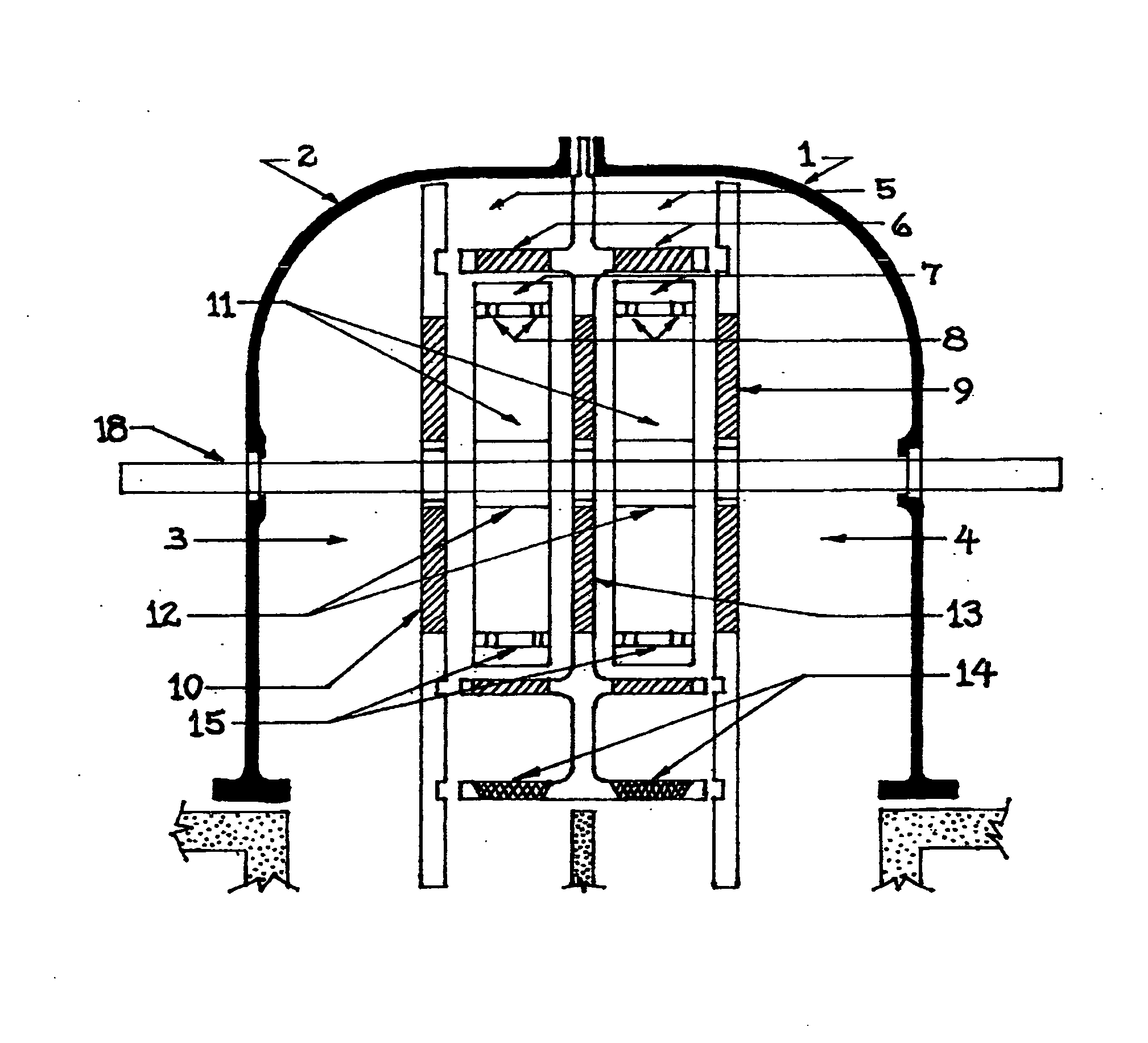
[0014]It is seen that the pressure containment dome is separated into four distinct chambers by the three bulkheads. The two outermost chambers (3&4) serve the primary duct to convey the air flow axially through the outboard guide vanes (9&10) to the turbine blades (11). The two inboard chambers (5) serve to convey the air flow through a series of orifice plates (14) with one-way flapper lids. The orifice plates reduce the ambient air pressure and increases velocity. This higher velocity air stream is then directed radially through a fixed stator composed of louvered collector guide vanes (6). These are oriented to distribute air in the direction of rotation to a plurality of directional collector vanes (7). The collector vanes are set perpendicular to the high velocity chamber (5) and are angled outward all around the annular rings (15) of each rotor set. These directional vanes serve two purposes: (a) to aid in the rotor's directional momentum in concert with the spinning airfoil blades (11) and, (b) to supply high velocity air to collector ports (8) located in the annulus (15).
[0015]The collector ports (8) force air into the hollow airfoil blades (11) in each rotor which then distributes the high velocity air through turbulators (16) and jets (17). The turbulators are located in the airfoil blades' upper surfaces and serve to reduce aerodynamic stalling by delaying flow separation in the blades' boundary layers. The jets are slotted orifices located lengthwise at the trailing edges of each airfoil blade. They slant the high velocity air downwards which aids in smoothing out vortex turbulence and also virtually increases the chord of each blade, improving the lift coefficient in a similar way that wing flaps on an aircraft will add lift at low airspeeds.

Problems solved by technology

Specifically, Oscillating Water Column (OWC) systems offer unique challenges.
This is unacceptable if a turbine has been designated to be the Power-Take-Off (PTO) device to spin an electrical generator.
This introduces performance and efficiency issues with regard to lift and stall characteristics.
The Wells design continues to be challenged by low efficiency, issues with low-speed operation, a small operating window, and an inability to self-start under many conditions.
Despite a large body of work from India and Japan attempting to refine the Wells Turbine, the design falls short of being a reliable and efficient PTO device.

Method used


Image

  • Wave energy turbine for oscillating water column systems
  • Wave energy turbine for oscillating water column systems
  • Wave energy turbine for oscillating water column systems

Examples


Embodiment Construction

[0048]The invention can be utilized in multiple applications where it could be employed by other WEC developers as a useful energy extraction PTO subsystem in their own OWC-based devices. Some of these applications could serve near and off shore systems such as anchored buoy farms where each buoy could support one or more turbines. Other applications would have the turbine attached to the legs or support structure of off shore oil platforms or other floating structures that have a suitable wave climate. Smaller turbine assemblies would work well as a power source for navigational or data acquisition buoys.

[0049]The most useful application for the current invention would be as a shore-based turbine, built into new or existing jetties, breakwaters or piers. Shore-based turbines can be housed in pre-cast concrete utility vaults where all the electrical generating and grid conversion devices can function together in a dry environment. The shore-based turbines would allow for easy mainte...


PUM


Abstract

The dual rotor turbine configuration efficiently harnesses oceanic wave energy within an oscillating water column system. The up and down movement of the waves creates a bi-directional pneumatic airflow which spins the twin turbine assemblies.The resulting rotary force is then utilized to drive two electrical generators simultaneously. Each turbine rotor set is composed of a radial array of identical asymmetrical airfoil blades (similar to NASA GA(W)-1). The two rotor sets are assembled as back-to-back mirror images. Both rotor sets are locked to a common axle by means of sprag-type freewheeling clutches. This configuration provides for smooth and continuous unidirectional movement of the axial drive line which drives the two generators.

Description

SEARCH REFERENCES[0001]U.S. Patent Documents6,968,683ShieldsNov. 29, 20055,191,225WellsMar. 2, 19934,221,538WellsSep. 9, 19804,405,866MasudaSep. 20, 19834,313,711LeeFeb. 2, 19825,577,882IstorikNov. 26, 19964,286,347ModisetteSep. 1, 19816,765,307GerberJul. 20, 20044,271,668McCormickJun. 9, 1981[0002]This application was preceded by a provisional patent application titled “Wave Energy Conversion Turbine for Oscillating Water Column Systems” filed on Aug. 12, 2010 and bearing application No. 61 / 401,340, customer number 99489.BACKGROUND OF THE INVENTION[0003]To improve the effectiveness of energy harvesting, ocean Wave Energy Conversion (WEC) devices need a more efficient bi-directional air turbine. Specifically, Oscillating Water Column (OWC) systems offer unique challenges. As the water level rises and falls within an OWC wave capture chamber, the resulting compressed air stream will reverse direction with every wave cycle. When a pneumatically driven turbine is exposed to this recipr...

Claims


Application Information

Patent Timeline
IPC IPC(8): F03B13/24F03B13/22
CPCF03B13/142F03B13/24F05B2210/404F05B2240/122F05B2240/14F05B2240/301F05B2260/4023Y02E10/32Y02E10/38Y02E10/30
Inventor HANNA, JOHN CLARK
Owner INYANGA TECH LTD
Learn More