
Imaging apparatus

a technology of imaging apparatus and generating frequency, which is applied in the field of imaging apparatus, can solve the problems of deteriorating user's convenience at the time of continuous shooting, and achieve the effect of improving the convenience of continuous shooting and reducing the frequency of generating images that fail

Inactive Publication Date: 2012-02-09
IMAGE PROCESSING TECH
View PDF5 Cites 10 Cited by
  • Summary
  • Abstract
  • Description
  • Claims
  • Application Information

AI Technical Summary

Benefits of technology

[0007]In view of the above problem, an imaging apparatus capable of improving user's convenience in the continuous shooting is provided. That is to say, an object is to provide the imaging apparatus which can avoid a situation that a plurality of images are continuously shot in a state that the user cannot recognize shooting timing in the continuous shooting.
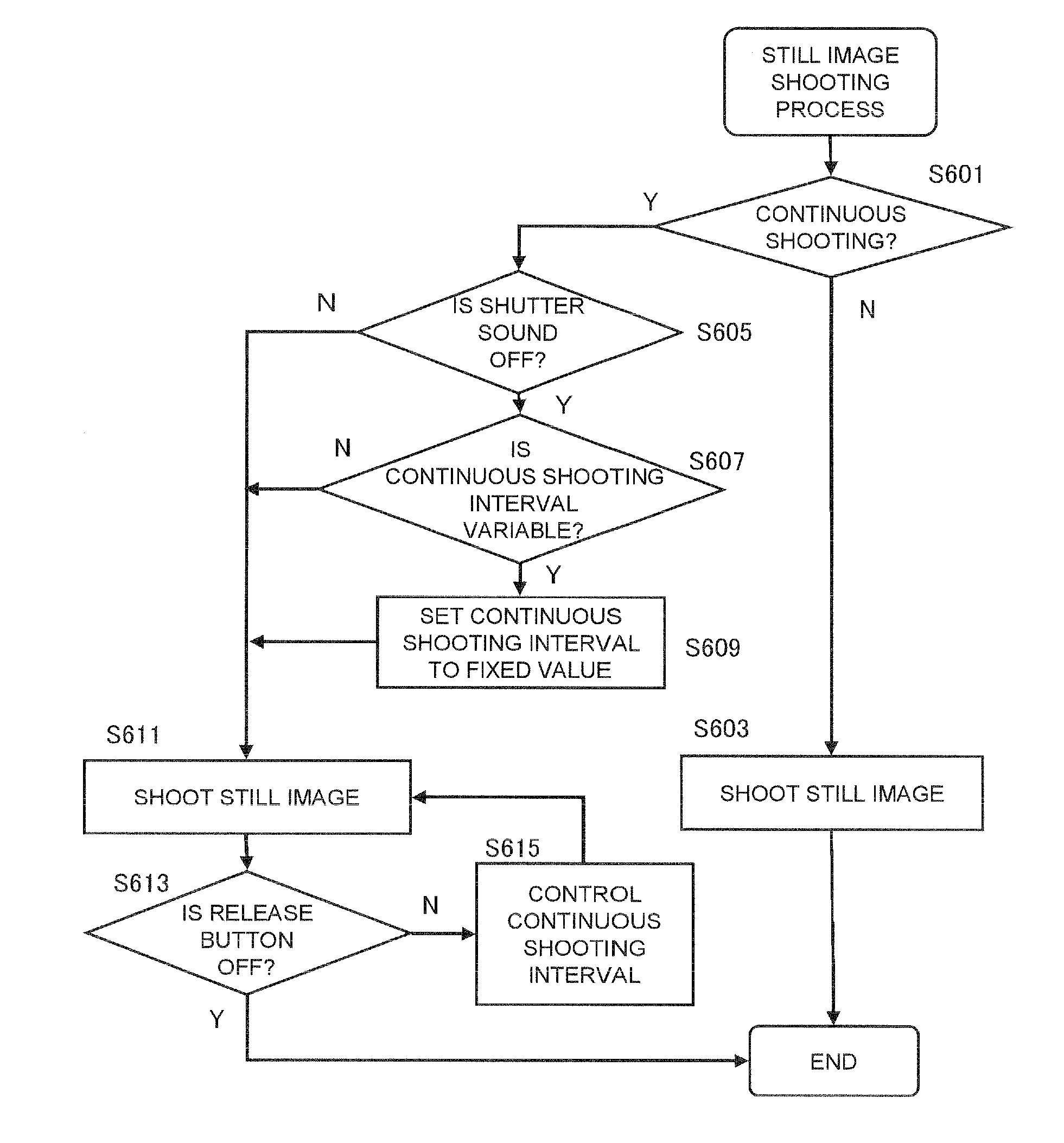
[0009]According to the aspect, in a case where the setting is made such that a predetermined sound (for example, a shutter sound) is not output, when the continuous shooting is tried to be performed at the variable shooting interval, a control is performed so as to prevent the continuous shooting operation at the variable shooting interval from being performed in the state that the predetermined sound according to the shooting operation is not output (for example, the shooting interval in the continuous shooting is set to a fixed value). As a result, a situation that a plurality of images are continuously shot in the state that the user cannot recognize the shooting timing can be avoided, thereby reducing a generating frequency of failing images. As a result, the imaging apparatus capable of improving the convenience of the continuous shooting can be provided.

Problems solved by technology

For this reason, it is difficult to determine a field angle during the continuous shooting, and thus preferable continuous images cannot be shot, thereby deteriorating user's convenience at the time of the continuous shooting.

Method used


Image

  • Imaging apparatus
  • Imaging apparatus
  • Imaging apparatus

Examples


first embodiment

[0018]1. Configuration of Digital Camera

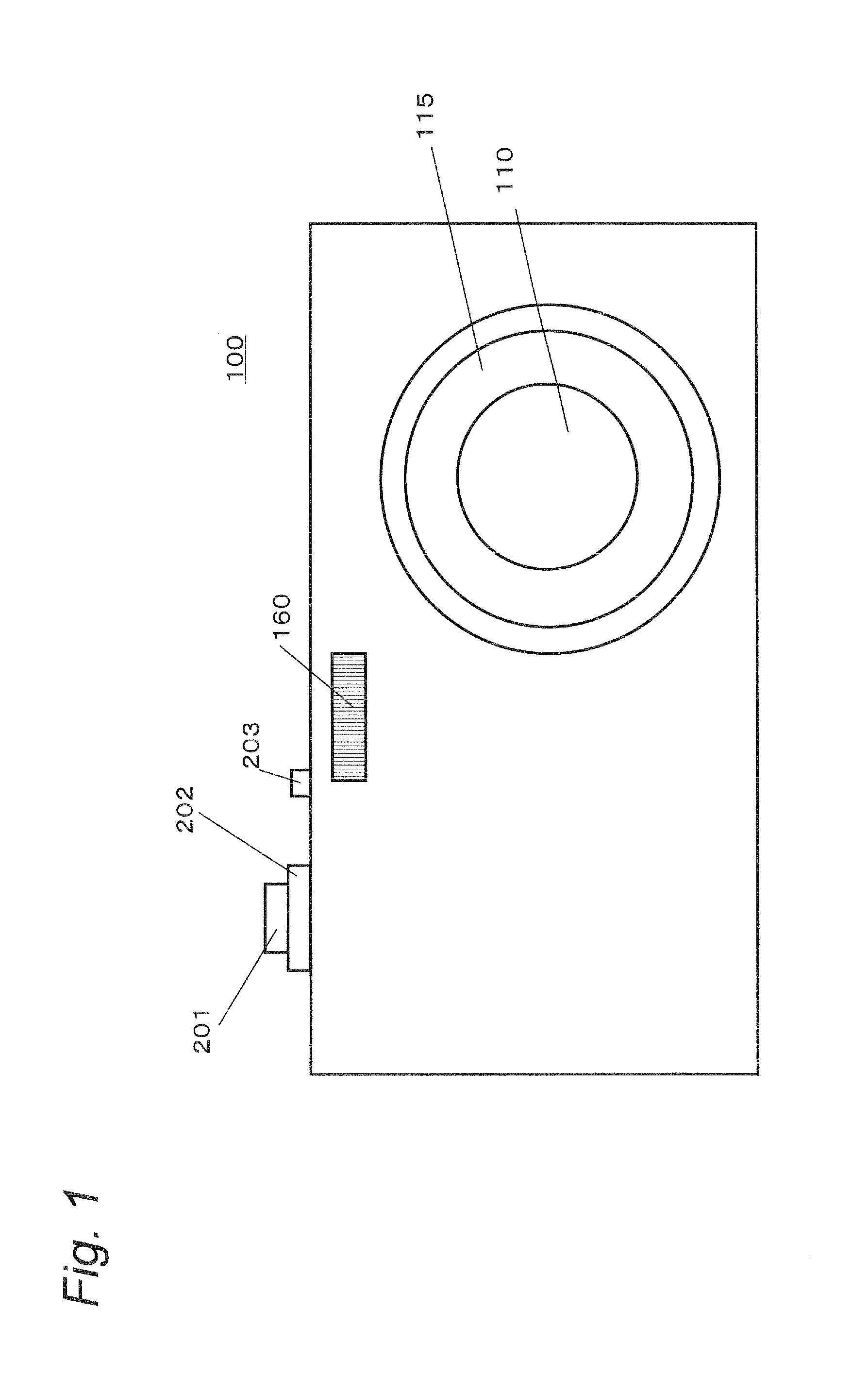
[0019]FIG. 1 is a front view illustrating the digital camera according to the first embodiment. The digital camera 100 has a lens barrel housing an optical system 110 at its front, and a flash 160. The digital camera 100 has operation buttons such as a still image release button 201, a zoom lever 202, and a power button 203 on its upper surface.

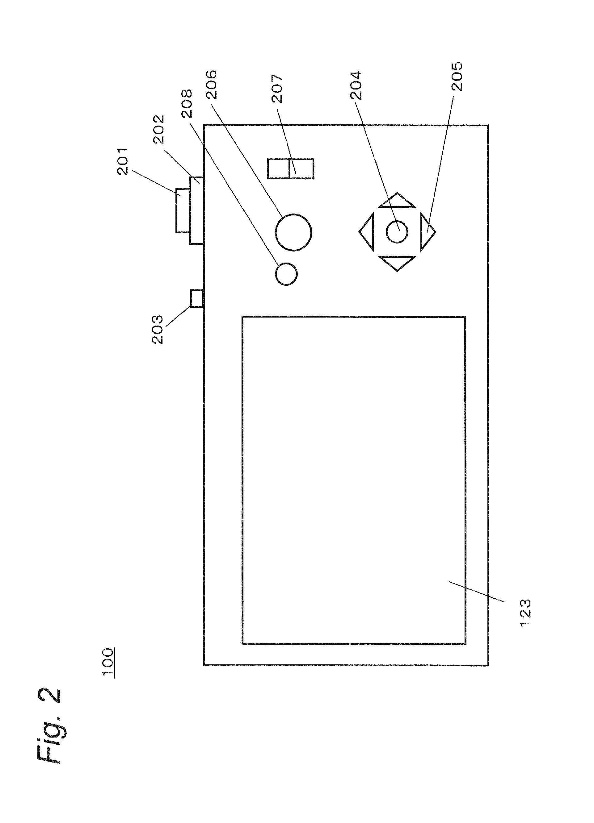
[0020]FIG. 2 is a rear view illustrating the digital camera 100. The digital camera 100 has a liquid crystal display (LCD) monitor 123 and operation buttons on its rear surface. The operation buttons include a center button 204, cross buttons 205, a moving image release button 206, mode changing-over switches 207, and a continuous shooting mode changing-over button 208.

[0021]FIG. 3 is an internal configuration diagram of the digital camera 100. The digital camera 100 takes a subject image formed via the optical system 110 using a CCD image sensor 120. The CCD image sensor 120 generates image information...


PUM


Abstract

An imaging apparatus includes an input unit configured to receive an instruction for starting a continuous shooting operation, a sound output unit configured to output a predetermined sound according to a shooting operation, and a controller configured to control output / non-output of the predetermined sound from the sound output unit according to a setting of sound output, and to control the continuous shooting operation. The setting of sound output includes an ON setting for outputting the predetermined sound from the sound output unit according to a start of the shooting operation and an OFF setting for non-outputting the predetermined sound from the sound output unit according to the start of the shooting operation. When receiving the instruction for starting the continuous shooting operation via the input unit with the setting of sound output being the OFF setting and the shooting interval in the continuous shooting operation being set to be variable, the controller performs a control so as to prevent the continuous shooting operation at the variable shooting interval from being performed in a state that the predetermined sound according to the shooting operation is not output.

Description

BACKGROUND[0001]1. Technical Field[0002]The technical field relates to an imaging apparatus capable of continuously recording (continuous shooting) still images, and more particularly to the imaging apparatus capable of changing a shooting interval during the continuous shooting.[0003]2. Related Art[0004]Imaging apparatus such as a digital camera that can record still image continuously (continuous shoot) while a release button is being pressed down is known. JP2000-10162A discloses an imaging apparatus that enables such continuous shooting. JP2000-10162A particularly discloses the imaging apparatus capable of changing a shooting interval during the continuous shooting according to a motion of a subject. This imaging apparatus has an imaging unit configured to capture a subject to output image information, a subject speed detector configured to detect a moving speed of the subject in a shooting region based on the image information output from the imaging unit, and a continuous shoo...

Claims


Application Information

Patent Timeline
Patent Type & Authority Applications(United States)
IPC IPC(8): G03B17/18G03B17/00G03B7/08H04N5/225H04N5/91H04N101/00
CPCG03B17/18G03B9/58H04N1/2145H04N1/215
Inventor ISHIDA, KEN
Owner IMAGE PROCESSING TECH
Learn More