Light scanning apparatus and image forming apparatus
a scanning apparatus and light beam technology, applied in the field of light beam scanning apparatus and image forming apparatus, can solve the problems of limited manufacturing accuracy, degrade image quality, and not a complete regular polygon, and achieve the effect of suppressing fluctuations in scanning magnification of light beams
- Summary
- Abstract
- Description
- Claims
- Application Information
AI Technical Summary
Benefits of technology
Problems solved by technology
Method used
Image
Examples
first embodiment
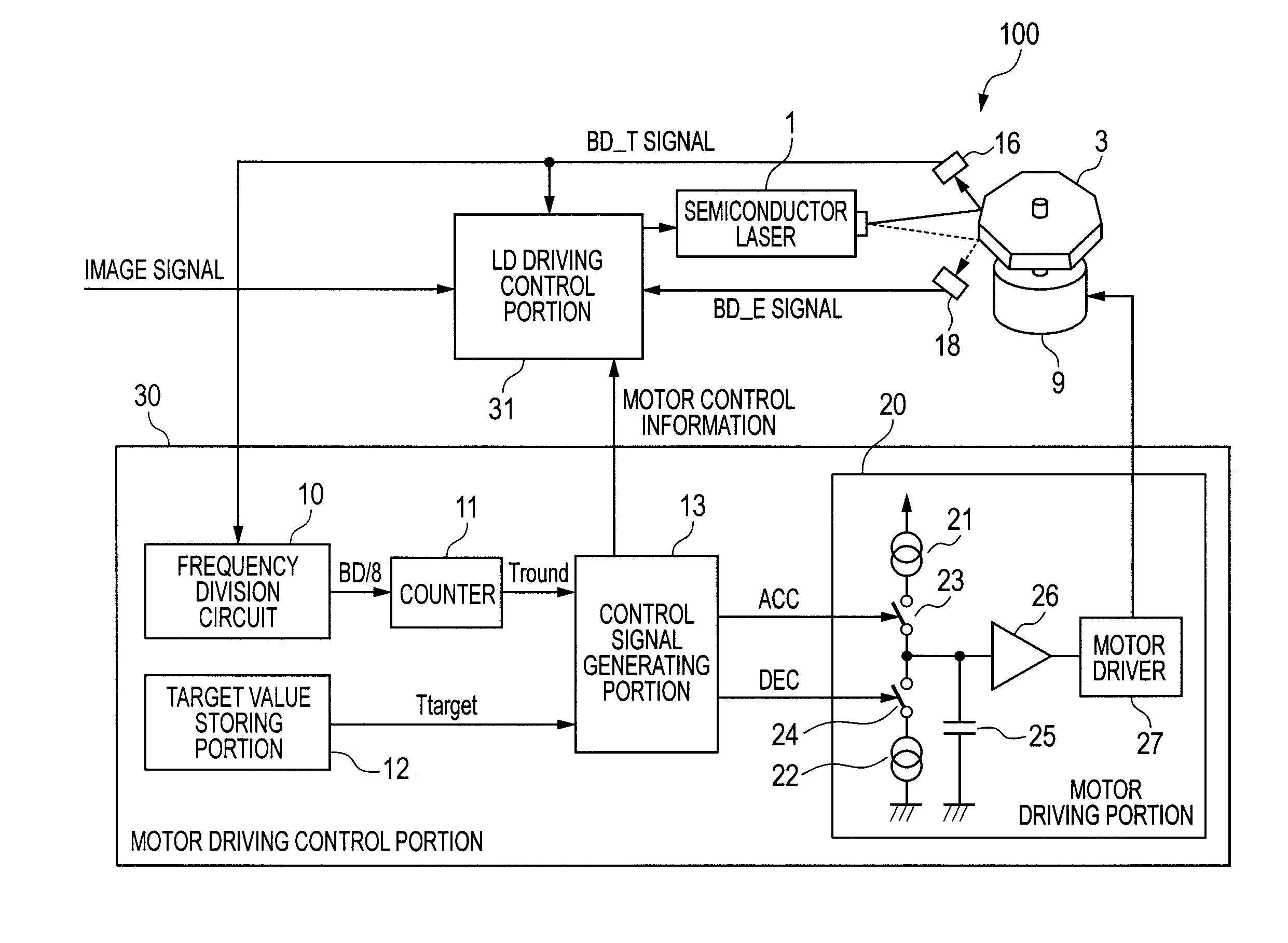
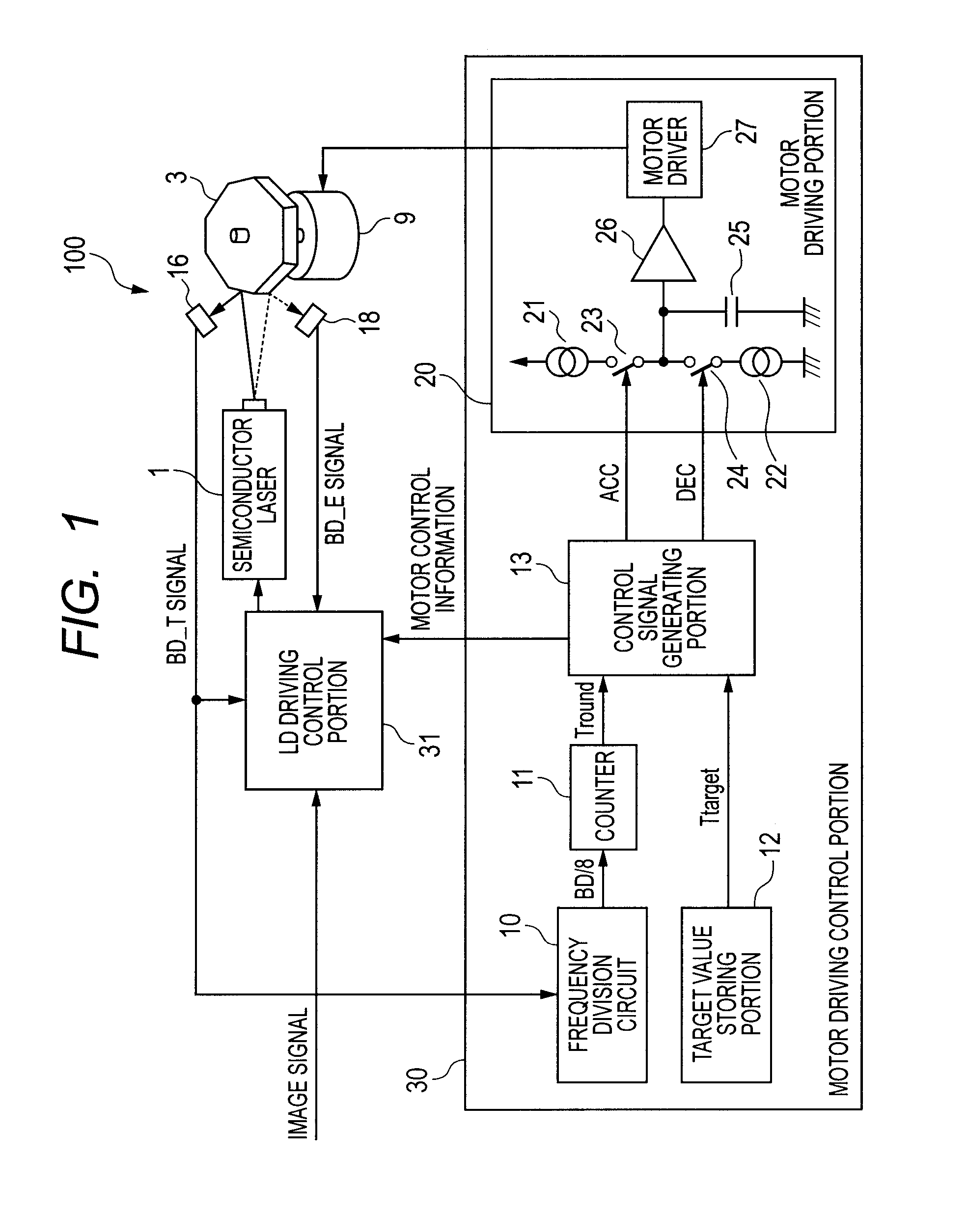
[0049]FIG. 1 is a diagram illustrating a light scanning apparatus 100 according to a first embodiment of the present invention. The light scanning apparatus 100 is provided in an image forming apparatus including an image forming portion that forms an image on a recording medium by an electrophotographic process.
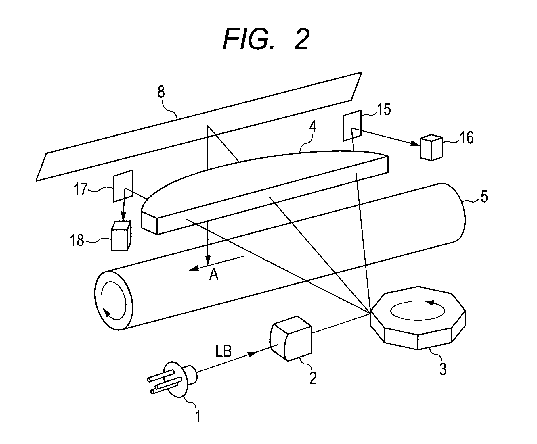
[0050]FIG. 2 illustrates a schematic structure of a light scanning system according to the first embodiment.
[0051]Note that, in FIG. 2, parts which are functionally equivalent to those in the related art illustrated in FIG. 14 are denoted by the same reference symbols and description thereof is thus omitted.
[0052]Referring to FIG. 2, a first BD reflecting mirror 15 and a first BD sensor 16 are disposed outside an image region on a scanning start side. Further, a second BD reflecting mirror 17 and a second BD sensor 18 are disposed outside the image region on a scanning end side. By measuring a time interval between detection by the first BD sensor and detection by the second...
second embodiment
[0093]FIG. 8 is a control block diagram according to a second embodiment of the present invention, schematically adding the driving motor 9 and the like. Note that, the structure of the laser beam scanning system is the same as that in the related art illustrated in FIG. 14 and description thereof is thus omitted. Further, parts which are similar to those in the first embodiment such as the motor driving control portion 30 are not described repeatedly.
[0094]A reference mark detecting portion 72 detects a reference mark 80 (FIG. 9) of the rotary polygon mirror 3 for discriminating the mirror surface. FIG. 9 is a top view of the rotary polygon mirror 3. FIG. 10 is a side view of the rotary polygon mirror 3.
[0095]Referring to FIG. 9, on the top surface of the rotary polygon mirror 3, the reference mark 80 in which only a part of the circumference of the reflectance is different from other part of the circumference is formed. With the rotary polygon mirror 3 being rotated, an optical se...
PUM
 Abstract
Description
Claims
Application Information
 - R&D
- Intellectual Property
- Life Sciences
- Materials
- Tech Scout
- Unparalleled Data Quality
- Higher Quality Content
- 60% Fewer Hallucinations
Browse by: Latest US Patents, China's latest patents, Technical Efficacy Thesaurus, Application Domain, Technology Topic, Popular Technical Reports.
© 2025 PatSnap. All rights reserved.Legal|Privacy policy|Modern Slavery Act Transparency Statement|Sitemap|About US| Contact US: help@patsnap.com


