Hydraulic brake system

Active Publication Date: 2012-02-02
HL MANDO CORP
View PDF12 Cites 8 Cited by
  • Summary
  • Abstract
  • Description
  • Claims
  • Application Information

AI Technical Summary

Benefits of technology

[0009]The present disclosure is directed to solving the problems of the related art, and an aspect of the present disclosure provides a hydraulic brake system capable of reducing periodic pressure pulsation resulting from operation of a pump.

Problems solved by technology

In the hydraulic brake system described above, although the orifice disposed near an outlet port of each pump reduces pressure pulsation caused by operation of the pump in a process of multiplying braking pressure, there is difficulty achieving complete reduction of the pressure pulsation since the orifice is provided to control a cross-sectional area of a flow passage for the purpose of damping reduction.
In this case, however, there is a problem of increase in manufacturing costs through increase of the weight and volume of the motor for improving performance of the motor.
Moreover, the peak of pressure pulsation continuously generated due to operation of the pump can act as a source of noise of the hydraulic brake system.

Method used


Image

  • Hydraulic brake system
  • Hydraulic brake system
  • Hydraulic brake system

Examples


Embodiment Construction

[0015]Hereinafter, exemplary embodiments of the present disclosure will be described in detail with reference to the accompanying drawings.

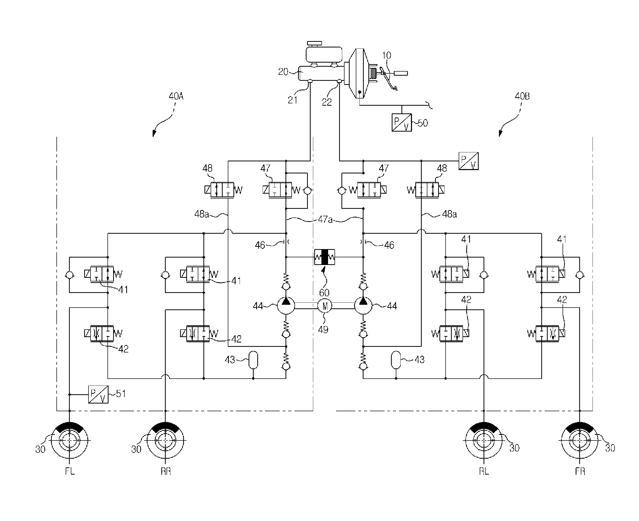
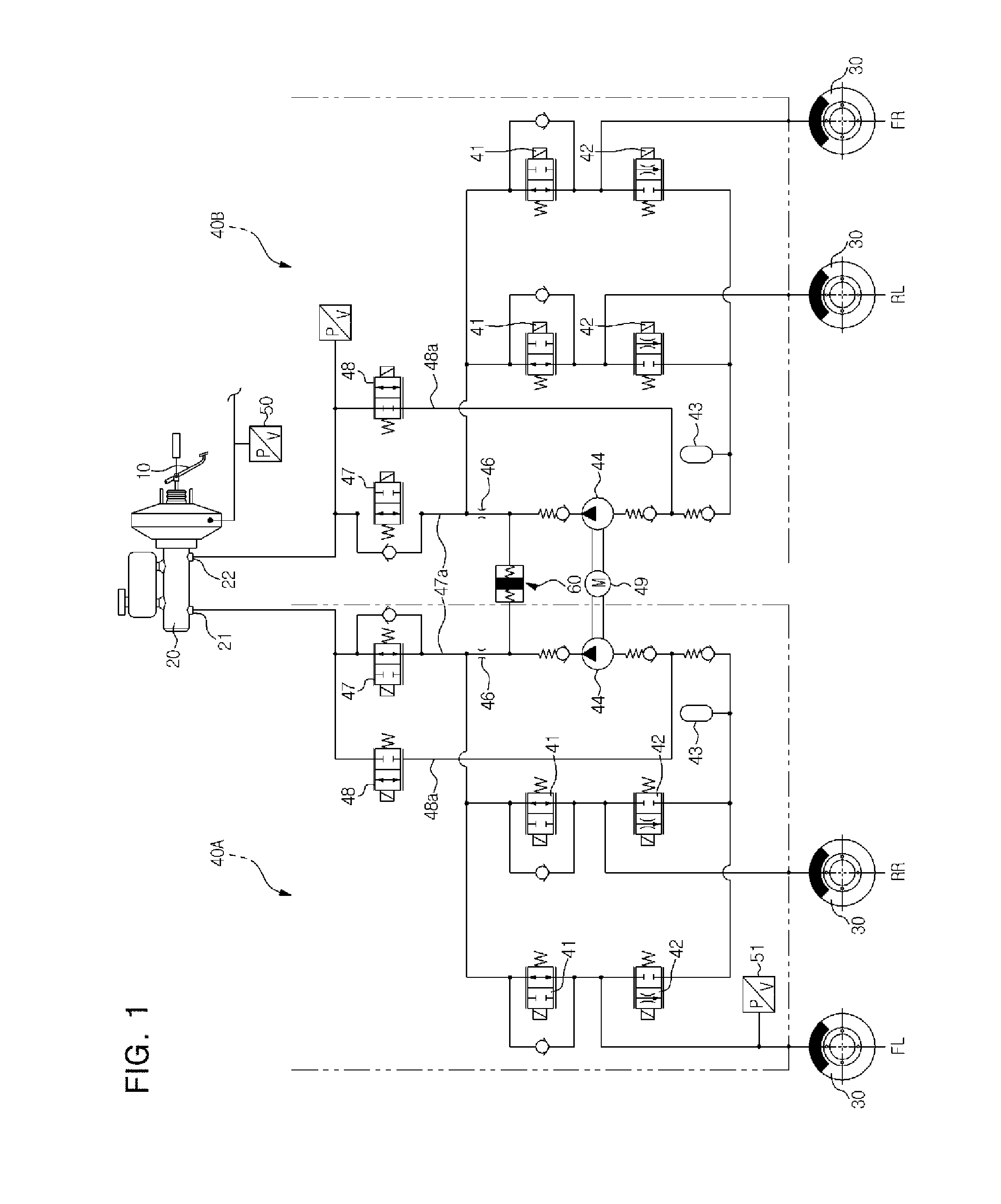
[0016]Referring to FIG. 1, a hydraulic brake system according to an exemplary embodiment of the present disclosure includes a brake pedal 10 receiving operational force of a driver, a brake booster 11 multiplying pedal force of the brake pedal 10 using a difference between a vacuum and atmospheric pressure, a master cylinder 20 generating pressure by the brake booster 11, a first hydraulic circuit 40A connecting a first port 21 of the master cylinder 20 to two wheel brakes 30 (or wheel cylinders) to control transmission of hydraulic pressure, and a second hydraulic circuit 40B connecting a second port 22 of the master cylinder 20 to the remaining two wheel brakes 30 to control transmission of hydraulic pressure. The first and second hydraulic circuits 40A, 40B are compactly installed in a hydraulic block (not shown).

[0017]Each of the first and se...


PUM


Abstract

Disclosed is a hydraulic brake system capable of reducing periodic pressure pulsation caused by operation of a piston. The hydraulic brake system includes a master cylinder generating braking hydraulic pressure by operation of a brake pedal, a wheel brake provided to each of front right and left wheels and rear right and left wheels of a vehicle to receive the braking hydraulic pressure from the master cylinder to generate braking force, a solenoid valve provided to each of an inlet and an outlet of each of the wheel brakes to control flow of the braking hydraulic pressure, a low pressure accumulator Jo temporarily storing oil, which is ejected from the wheel brakes during operation of the solenoid valves, a pump compressing the oil stored in the low pressure accumulator such that the oil is ejected towards the wheel brakes or the master cylinder as needed, and an orifice disposed near an outlet port of the pump. Further, a damper unit is disposed between the outlet port of the pump and the orifice to reduce pressure pulsation caused by operation of the piston, thereby improving product reliability through noise reduction during brake control.

Description

CROSS REFERENCE TO RELATED APPLICATION[0001]This application claims priority from and the benefit of Korean Patent Application No. 10-2010-0072658, filed on Jul. 28, 2010, which is hereby incorporated by reference for all purposes as if fully set forth herein.BACKGROUND[0002]1. Technical Field[0003]The present disclosure relates to a hydraulic brake system, and more particularly, to a hydraulic brake system capable of reducing pressure pulsation caused by operation of a piston.[0004]2. Description of the Related Art[0005]A vehicle is necessarily fitted with a brake system. Recently, various kinds of brake systems have been suggested to obtain stronger and more stable braking force. Such brake systems include an anti-lock brake system (ABS) that prevents slippage of a wheel during braking, a brake traction control system (BTCS) that prevents slippage of a driven wheel upon rapid start or rapid acceleration of a vehicle, a vehicle dynamic control system (VDC) that is a combination of ...

Claims


Application Information

Patent Timeline
IPC IPC(8): B60T11/16
CPCB60T8/4872B60T8/4068
Inventor PARK, SEUNG YOUNGCHOI, SEONG HO
Owner HL MANDO CORP
Why Eureka
Try Eureka