
Network system, control method for the same, and controller

a network system and control method technology, applied in the field of network system and control method of the same, can solve the problem that the packet distribution device itself becomes a bottleneck, and achieve the effect of easy secure scalability of the relay processing devi

Inactive Publication Date: 2012-01-26
NEC CORP
View PDF9 Cites 160 Cited by
  • Summary
  • Abstract
  • Description
  • Claims
  • Application Information

AI Technical Summary

Benefits of technology

[0008]By way of generalization, not only the packet distribution device but also a device such as a load balancer (load balancing device) and a fire wall will be hereinafter referred to as a “relay processing device”. An object of the present invention is to easily secure scalability of the relay processing device in a network system.
[0012]According to the present invention, it is possible to easily secure scalability of the relay processing device in a network system.

Problems solved by technology

In this case, however, the packet distribution device itself becomes a bottleneck.

Method used


Image

  • Network system, control method for the same, and controller
  • Network system, control method for the same, and controller
  • Network system, control method for the same, and controller

Examples


Embodiment Construction

[0032]Exemplary embodiments of the present invention will be described below with reference to the attached drawings.

[0033]1. Network System

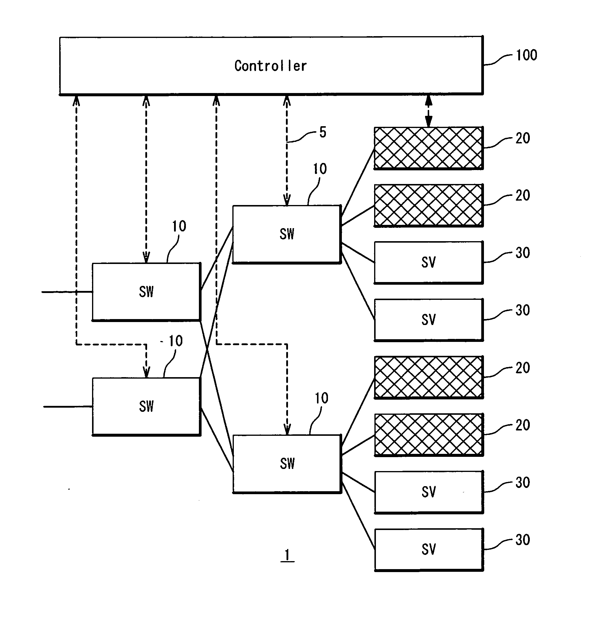
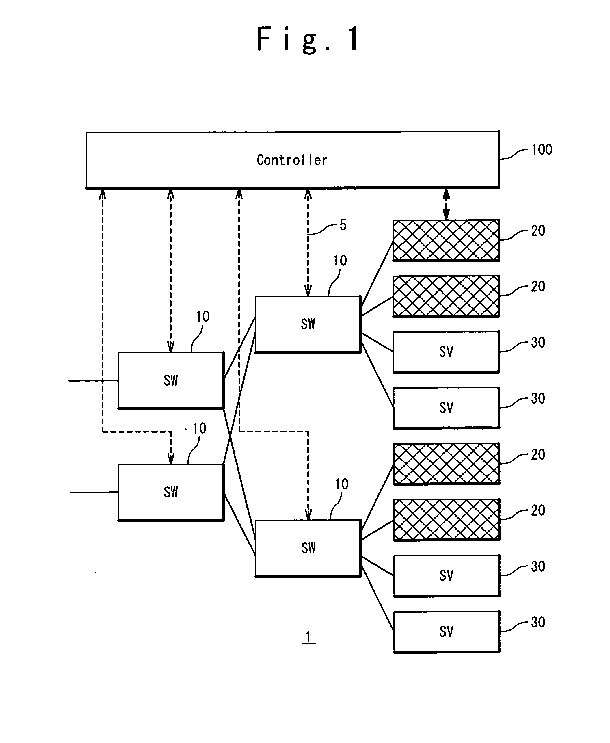
[0034]FIG. 1 is a block diagram showing a configuration example of a network system 1 according to an exemplary embodiment. The network system 1 has a plurality of switches 10, a plurality of relay processing devices 20, a plurality of servers 30 and a controller 100.

[0035]The relay processing devices 20 and the servers 30 are connected to a network through the switches 10. The relay processing device 20 is a dedicated device for handling a flow addressed to the server 30. The relay processing device 20 is exemplified by a network appliance such as a load balancer (load balancing device) and a fire wall. The network appliance is achieved by a dedicated hardware or by implementing software in a general-purpose server. Alternatively, the network appliance may be achieved by implementing software in a virtual machine on a general-purpose server (wh...


PUM


Abstract

In a network system, each server is assigned to at least one relay processing devices. A plurality of switches are arranged in a network and a controller controls the switches. Specifically, the controller designs, in response to a request from a request source switch, a route of a flow from the request source switch to a destination address. Here, the controller refers to assignment information indicating an assignment relationship between servers and relay processing devices to select, as a target, any one relay processing device assigned to a server specified by the destination address, and designs the route so as to include the target. Then, the controller instructs each switch on the designed route to set the flow table such that a packet is forwarded along the designed route.

Description

CROSS-REFERENCE TO RELATED APPLICATION[0001]This is a continuation of International Application No. PCT / JP2010 / 068504, filed on Oct. 20, 2010.TECHNICAL FIELD[0002]The present invention relates to a network system and a control method for the same.BACKGROUND ART[0003]Regarding a network system, load balancing is one of important issues. For example, regarding a nonstructural network such as an enterprise network, a technique described in Non-Patent Literature 1 achieves comprehensive load balancing by considering a network congestion state and a server load state.[0004]Patent Literature 1 (Japanese Patent Publication JP-2005-64882) discloses a higher-order layer processing system. In the higher-order layer processing system, a plurality of higher-order layer processing devices are arranged in parallel in order to secure scalability of the system. In order to equally use resources of the higher-order layer processing devices, a packet distribution device is provided at a former stage ...

Claims


Application Information

Patent Timeline
IPC IPC(8): G06F15/16
CPCH04L45/38
Inventor UENO, HIROSHI
Owner NEC CORP
Learn More