
Illumination unit for vehicle headlights and vehicle headlights

a technology for vehicle headlights and illumination units, which is applied in semiconductor devices for light sources, lighting and heating apparatus, transportation and packaging, etc. it can solve the problems of comparatively labor-intensive and expensive production of metallic housings, and achieve the effect of less expensiv

Active Publication Date: 2012-01-26
OSRAM BETVERWALTUNG GMBH
View PDF15 Cites 74 Cited by
  • Summary
  • Abstract
  • Description
  • Claims
  • Application Information

AI Technical Summary

Benefits of technology

[0002]It is the object of the invention to provide a generic illumination unit having a less expensive housing and affording electromagnetic shielding for the electrical components of the operating circuit that are arranged in the housing.
[0005]The electrically conductive inner layer and the shielding means of the housing which are connected to the aforesaid electrically conductive inner layer via the at least one electrical contact surface on the surface of the assembly board effect inexpensive electromagnetic shielding of the interior space of the housing since as a result of these measures the housing can be manufactured from plastic, for example using injection-molding technology, and need not be embodied as a metal housing. Preferably those components of the operating circuit of the light-emitting diode device are arranged in the thus shielded interior space of the housing and which during operation generate signals having a high-frequency component which could interfere with the radio or television reception in the vehicle or interfere with electronic systems.
[0006]The at least one electrical contact surface is arranged on at least one side of the assembly board. Preferably the at least one electrical contact surface also extends over the edge of the assembly board onto the other side of the assembly board in order to ensure a good connection with the electromagnetic shielding means and the electrically conductive layer of the assembly board lying at ground reference potential. In the case of a soldered connection between the at least one electrical contact surface and the electromagnetic shielding means it is sufficient for the at least one electrical contact surface to be arranged on one side of the assembly board only. The aforesaid electrically conductive inner layer at ground reference potential is preferably a layer of the preferably multilayered assembly board extending over the entire area of the assembly board. The electrical contacting of said inner layer at ground reference potential with the at least one electrical contact surface of the assembly board can advantageously be provided by means of one or more metallic pins which are inserted into continuous holes drilled in the assembly board in the area of the annular electrical contact surface.
[0018]The aforesaid housing section consisting of electrically conductive plastic advantageously forms a supporting layer for the at least one electrical contact surface in order to enable said housing section to be electrically connected to the ground reference potential of the operating circuit in a simple manner.

Problems solved by technology

However, production of the metallic housing is comparatively labor-intensive and costly.

Method used


Image

  • Illumination unit for vehicle headlights and vehicle headlights
  • Illumination unit for vehicle headlights and vehicle headlights
  • Illumination unit for vehicle headlights and vehicle headlights

Examples


Embodiment Construction

[0020]The invention is explained in more detail below with reference to several exemplary embodiments. In the figures:

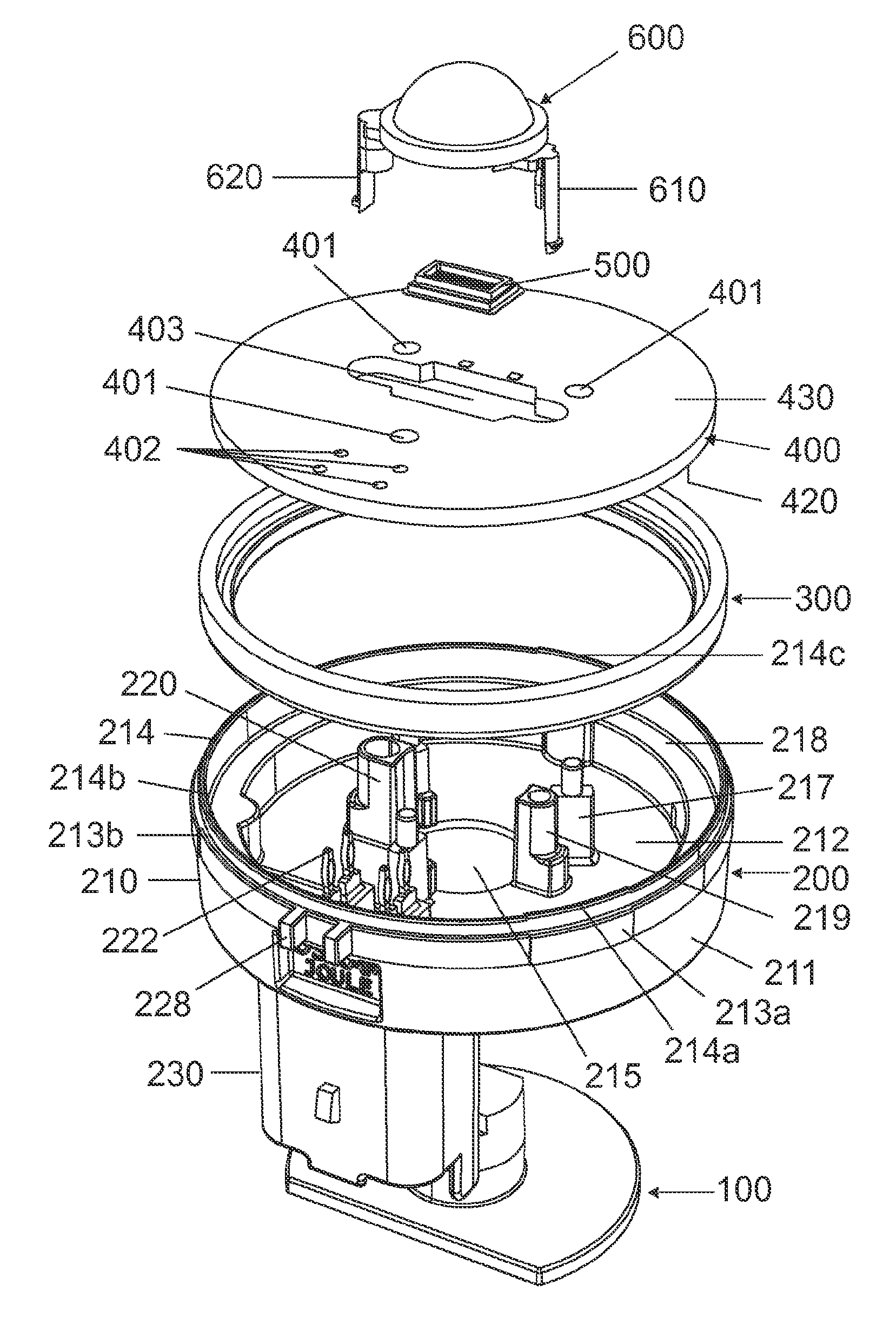
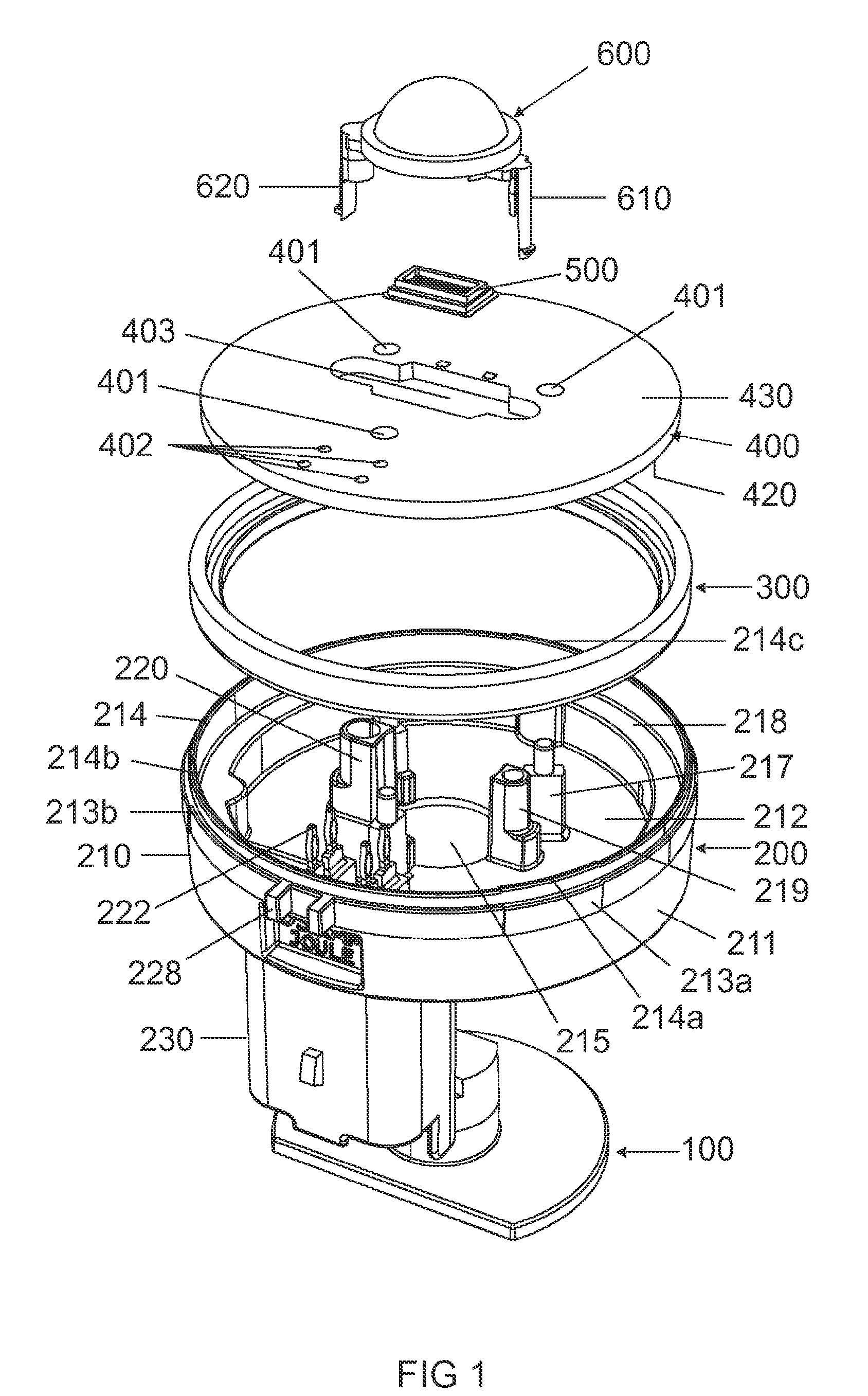
[0021]FIG. 1 is a schematic illustrating all the components of the illumination unit according to the first exemplary embodiment of the invention in an exploded view of the illumination unit

[0022]FIG. 2 shows a side view of the housing of the illumination unit of the housing illustrated in FIG. 1

[0023]FIG. 3 shows a front view of the housing illustrated in FIG. 2

[0024]FIG. 4 shows a rear view of the housing illustrated in FIGS. 2 and 3

[0025]FIG. 5 shows a side view of the metallic heatsink of the illumination unit depicted in FIG. 1

[0026]FIG. 6 shows a front view of the metallic heatsink illustrated in FIG. 5

[0027]FIG. 7 shows a perspective view of the metallic heatsink illustrated in FIGS. 5 and 6

[0028]FIG. 8 shows a side view of the primary lens of the illumination unit illustrated in FIG. 1

[0029]FIG. 9 shows a perspective view of the illumination unit illustrated ...


PUM


Abstract

An illumination unit for vehicle headlights may include a light-emitting diode device, a housing and an assembly board on which components of an operating circuit for operating the light-emitting diode device are arranged, wherein the housing and the assembly board define an interior space, wherein the assembly board has at least one electrically conductive inner layer that is connected to a ground reference potential of the operating circuit and on its surface the assembly board has at least one electrical contact surface which is contacted with at least one electrically conductive inner layer, and the housing has an electromagnetic shielding structure configured to provide electromagnetic shielding of the interior space, wherein the electromagnetic shielding structure is connected to the at least one electrical contact surface.

Description

I. PRIOR ART [0001]An illumination unit of said type is disclosed in WO 2008 / 065030 A1, for example. Said specification describes an illumination unit for a vehicle headlight having a light-emitting diode device and a metallic housing which at least partially encloses the light-emitting diode device and which is provided with fastening means allowing the illumination unit to be installed in a vehicle headlight. Said fastening means are embodied so as to enable the light-emitting diode chips to be aligned with respect to the lens system of the vehicle headlight. The metallic housing can be connected to a heatsink in order to cool the light-emitting diode chips and serve to provide electromagnetic shielding of components of an operating circuit that are arranged therein. However, production of the metallic housing is comparatively labor-intensive and costly.II. SUMMARY OF THE INVENTION [0002]It is the object of the invention to provide a generic illumination unit having a less expensi...

Claims


Application Information

Patent Timeline
Patent Type & Authority Applications(United States)
IPC IPC(8): F21V15/01
CPCF21K9/00F21Y2101/02F21V25/00F21S48/1109F21Y2115/10F21S41/192F21S45/48
Inventor BIEBL, ALOISFREY, PETERVOLLMER, RALF
Owner OSRAM BETVERWALTUNG GMBH
Learn More