
Radiological characterization device protected against parasitic ionizing radiation sources

a radiation source and radiation characterization technology, applied in radiation measurement, instruments, photometry, etc., can solve the problem of masking hot spots of lower intensity

Active Publication Date: 2012-01-19
COMMISSARIAT A LENERGIE ATOMIQUE ET AUX ENERGIES ALTERNATIVES
View PDF1 Cites 3 Cited by
  • Summary
  • Abstract
  • Description
  • Claims
  • Application Information

AI Technical Summary

Benefits of technology

[0006]The aim of the present invention is to propose a radiological characterisation device that does not have the above limitations and difficulties, and in particular that is capable of characterising ionising radiation sources even of lower intensity in the presence of more intense ionising radiation sources without being interfered with by parasitic noise.
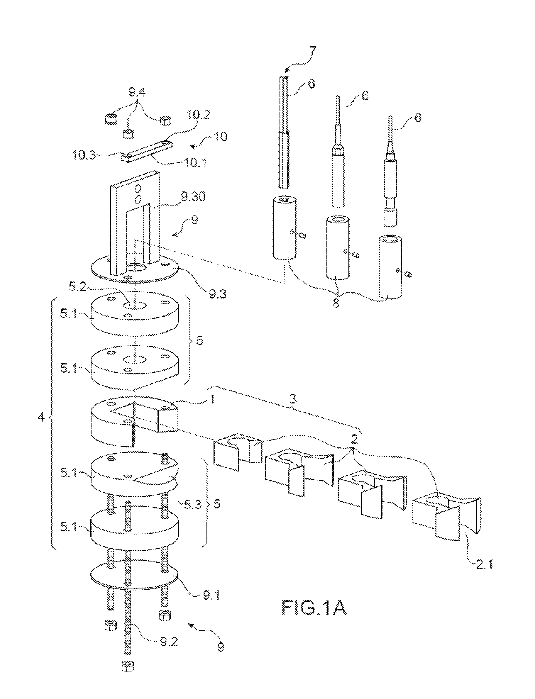
[0009]To achieve this, the present invention is a radiological characterisation device comprising at least one collimated radiological measuring probe, a sensitive end of which is placed in an interchangeable collimator having an observation field and an opening. The collimator is carried by a collimator holder and the assembly consisting of collimator and collimator holder is inserted in a stack between two shielding screens, the screens providing the shielding being exchangeable so as to adjust the thickness thereof, the assembly consisting of collimator and collimator holder and the shielding screens providing protection for the probe vis-à-vis parasitic ionising radiation coming from ionising radiation sources situated outside the observation field of the collimator.
[0013]The radiological characterisation device preferably also comprises a removable probe holder in which the probe is placed, the probe holder, when it is housed in the collimator, making it possible to position the sensitive end of the probe in the collimator.
[0015]Advantageously, each shielding screen comprises one or more shielding plates; when there are several plates, they are in a stack. It is thus possible to adjust the thickness of the shielding screen.
[0019]It is possible to provide means of locking the shielding screens in terms of rotation and translation with respect to the collimator holder and collimator.
[0021]It is preferable also to provide means of locking the probe when it is in place in the collimator, so as to be able to move the characterisation device without any problems.

Problems solved by technology

The drawback of this device is that, in operation, hot spots of lower intensity may be masked by more intense hot spots outside the field of observation of the collimator.

Method used


Image

  • Radiological characterization device protected against parasitic ionizing radiation sources
  • Radiological characterization device protected against parasitic ionizing radiation sources
  • Radiological characterization device protected against parasitic ionizing radiation sources

Examples


Embodiment Construction

[0033]Reference will be made to FIG. 1A, which is an exploded view of an example of a radiological characterisation device according to the invention. FIG. 1B shows a transverse section of the same radiological characterisation device according to the invention. It comprises a collimator holder 1 intended to accept a collimator 2. The collimator 2 is substantially in a U shape with a bottom from which two arms start that contribute to delimiting the opening 2.1 of the collimator 2. The collimator holder 1 can be substantially in a U or C shape, the bottom of the U of the collimator being housed in the collimator holder 1. Thus the collimator 2 is exchangeable and the collimator holder 1 is able to accept collimators 2 having openings 2.1 of different sizes but the same base. FIG. 1A shows a set of four collimators 2 that can be installed on the collimator holder 1 each in their turn. These four collimators 2 have openings 2.1 of different sizes, corresponding for example to angles o...


PUM


Abstract

A radiological characterization device comprising at least one collimated radiological measuring probe, a sensitive end of which is placed in an exchangeable collimator having an opening and a field of observation. The collimator is carried by a collimator holder, the assembly consisting of collimator and collimator holder being inserted in a stack between two shielding screens, the shielding screens being exchangeable so as to adjust the thickness thereof, the assembly consisting of collimator and collimator holder and the shielding screens providing protection for the probe vis-à-vis parasitic ionizing radiation coming from ionizing radiation sources situated outside the field of observation of the collimator.

Description

TECHNICAL FIELD[0001]The present invention concerns a phased array ultrasonic contact transducer.TECHNICAL FIELD[0002]The present invention concerns a radiological characterisation device protected against parasitic ionising radiation sources. Radiological characterisation means that it will be possible with the device, to make quantitative measurements, that is to say of dose rate, and measurements on the quality of radioelements present by means of spectrometry.[0003]Work in hostile environments is frequent in the nuclear industry, in particular in operations of dismantling nuclear installations. These operations are of course framed by rules, practices and optimisation methods, for example by the application of the ALARA (as low as reasonably achievable) principle. This principle was established by the industry in order to reduce exposure to ionising radiation so that it is as low as possible having regard to economic and social factors. In practice, the technical operations depe...

Claims


Application Information

Patent Timeline
Patent Type & Authority Applications(United States)
IPC IPC(8): G01T1/178G01T1/02
CPCG01T7/00
Inventor GIRONES, PHILIPPEBRENNEIS, CHRISTOPHELAMADIE, FABRICEDUCROS, CHRISTIAN
Owner COMMISSARIAT A LENERGIE ATOMIQUE ET AUX ENERGIES ALTERNATIVES
Learn More