Signal evaluating device and signal evaluating method

a signal evaluation and signal technology, applied in the direction of optical radiation measurement, instruments, using reradiation, etc., can solve the problems of large amount of calculation required, difficult to evaluate whether the output of the signal extracting circuit is noise or a signal, and no easy method for achieving an evaluation of whether, etc., to achieve low calculation overhead, easy evaluation, and short evaluation period

Inactive Publication Date: 2012-01-12
YAMATAKE HONEYWELL CO LTD
View PDF1 Cites 6 Cited by
  • Summary
  • Abstract
  • Description
  • Claims
  • Application Information

AI Technical Summary

Benefits of technology

[0018]Given the present invention, the provision of binarizing means for binarizing an input signal, run length measuring means for measuring the run length of the sign that is the result of binarizing of the input signal during the evaluating interval, using the output of the binarizing means as the input, each time the sign changes; and evaluating means for calculating, from the measurement results of the run length measuring portion, a distribution wherein the noise frequency distribution included in the input signal during the evaluating interval is assumed to be a geometric distribution, and for evaluating whether or not the input signal is valid through comparing the calculated frequency to the run length frequency obtained from the measurement results by the run length measuring portion enables easy evaluation of whether or not an input signal is valid. In the present invention, no frequency analyzing technique, such as FFT, is used, thus making it possible to evaluate in a short period of time and with low calculation overhead, whether or not an input signal is valid.
[0019]Additionally, in the present invention, the provision of binarizing means for binarizing an input signal, run length measuring means for measuring the run length of the sign that is the result of binarizing of the input signal during the evaluating interval, using the output of the binarizing means as the input, each time the sign changes; and evaluating means for calculating, from the meas...

Problems solved by technology

In MHPs, which are self-coupled signals, the signal components vary depending on the physical quantity and on the signal component, making the evaluation of whether that which is outputted from the signal extracting circuit is noise or a signal difficult, and there has been no known method for evaluating noise versus signals, that is, no easy method for achieving an evaluation of whether or not an inputted signal is valid.
Conventionally, methods have been considered that use frequency analysis, such a...

Method used


Image

  • Signal evaluating device and signal evaluating method
  • Signal evaluating device and signal evaluating method
  • Signal evaluating device and signal evaluating method

Examples


Embodiment Construction

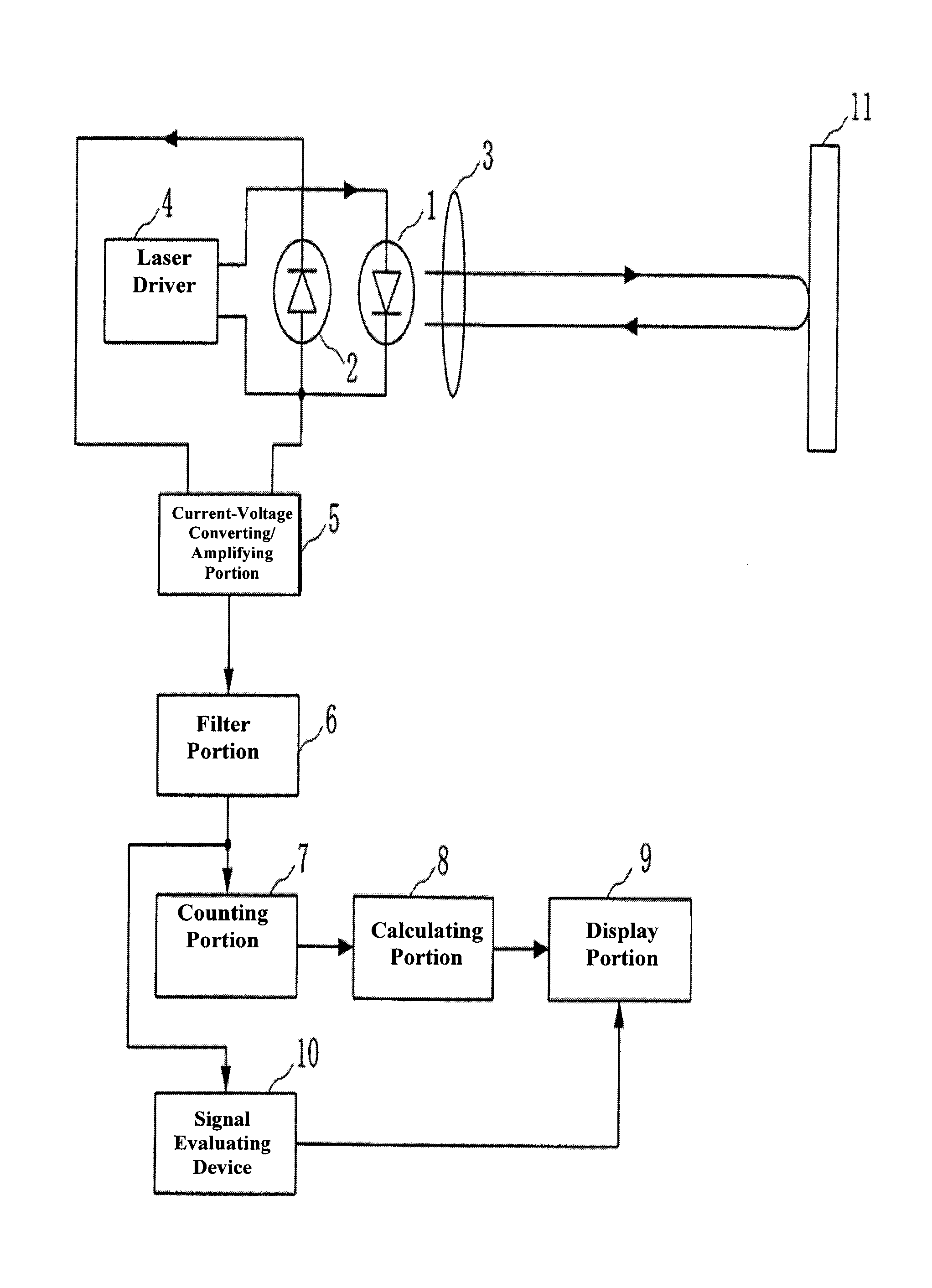
[0031]Forms for carrying out the present invention is explained below in reference to the figures. FIG. 1 is a block diagram illustrating a structure of a self-coupled laser sensor according to an example.

[0032]The self-coupling laser sensor in FIG. 1 includes a semiconductor laser 1 for emitting a laser beam at a object 11 that is the subject of the measurement; a photodiode 2 for converting the optical power of the semiconductor laser 1 into an electric signal; a lens 3 for focusing and emitting light from the semiconductor laser 1, and for focusing and injecting into the semiconductor laser 1 the return light from the object 11; a laser driver 4 that serves as oscillating wavelength modulating means for driving the semiconductor laser 1; a current-voltage converting / amplifying portion 5 for converting the output current from the photodiode 2 into a voltage and for amplifying that voltage; a filter portion 6 for eliminating the carrier wave from the output voltage of the current-v...


PUM


Abstract

A signal evaluating device comprises: a binarizing portion for binarizing an input signal; a run length measuring portion for measuring the run length of the input signal during the evaluating interval, using the output of the binarizing portion as the input; and evaluating means for calculating, from the measurement results of the run length measuring portion, a distribution wherein the noise frequency distribution included in the input signal during the evaluating interval is assumed to be a geometric distribution, and for evaluating whether or not the input signal is valid through comparing the calculated frequency to the run length frequency obtained from the measurement results by the run length measuring portion (probability calculating portion, noise frequency calculating portion, and validity evaluating portion).

Description

CROSS REFERENCE TO RELATED APPLICATIONS[0001]The present application claims priority under 35 U.S.C, §119 to Japanese Patent Application No. 2010-154550, filed Jul. 7, 2010, which is incorporated herein by reference.FIELD OF TECHNOLOGY[0002]The present invention relates to a signal evaluating device and signal evaluating method for evaluating whether or not an input signal is valid.BACKGROUND OF THE INVENTION[0003]Conventionally, there have been proposals for self-coupling laser sensors that use the self-coupling effect of a semiconductor laser (See Japanese Unexamined Patent Application Publication 2006-313080 (“JP '080”)). The structure of the self-coupling laser sensor is illustrated in FIG. 9. The self-coupling laser sensor of FIG. 9 includes a semiconductor laser 201 for emitting a laser beam at an object 210; a photodiode 202 for converting the optical output of the semiconductor laser 201 to an electric signal; a lens 203 for focusing the beam from the semiconductor laser 201...

Claims


Application Information

Patent Timeline
IPC IPC(8): G06F19/00G01S17/34
CPCG01S7/4916G01J1/02G01S17/325G01S7/493G01S17/34
Inventor UENO, TATSUYA
Owner YAMATAKE HONEYWELL CO LTD
Why Eureka
Try Eureka